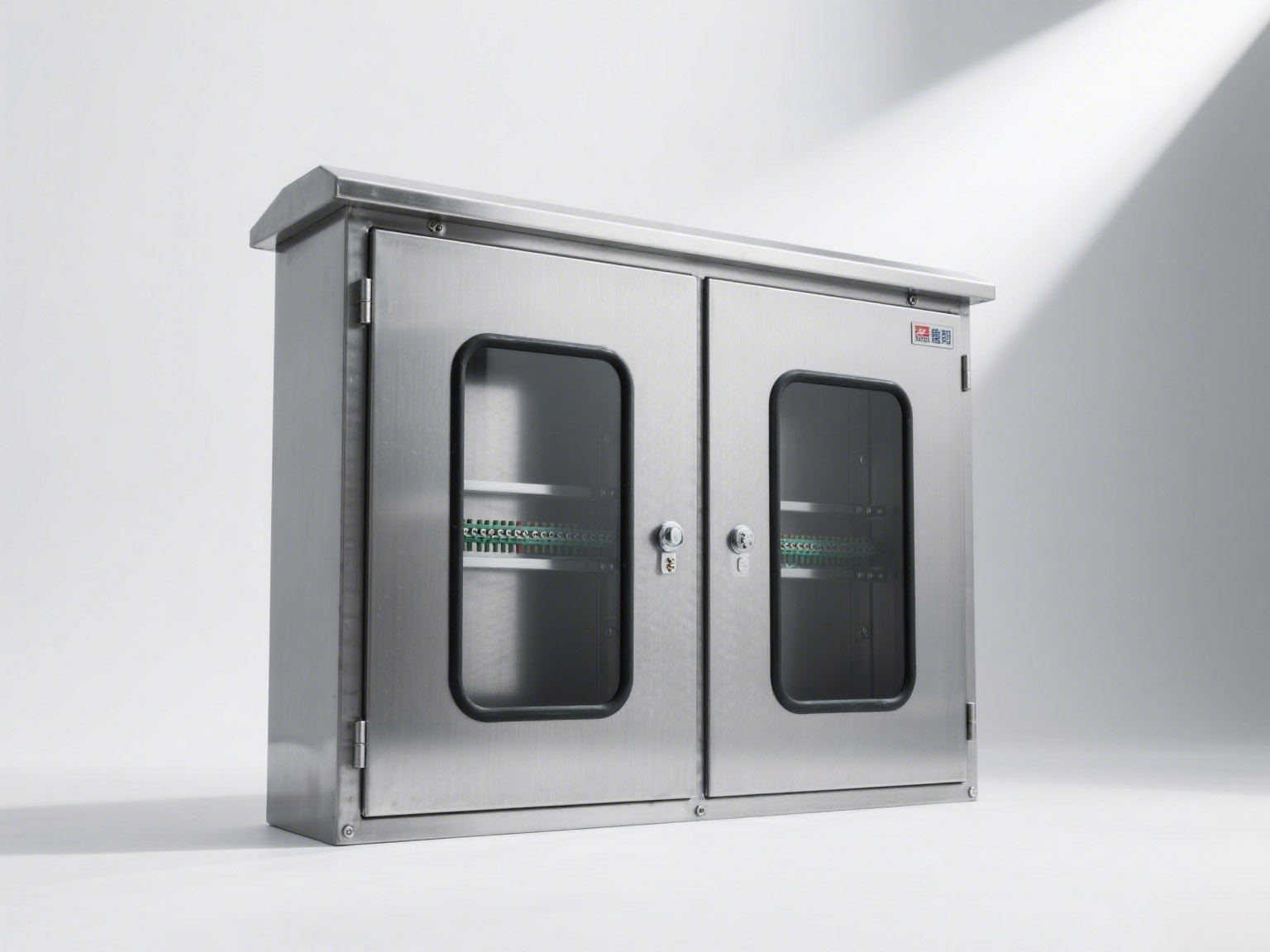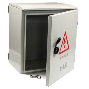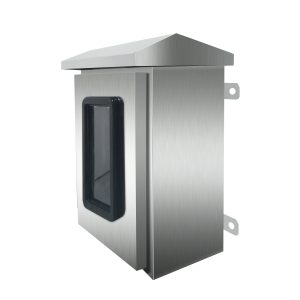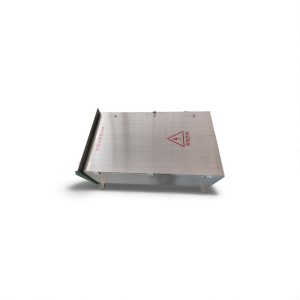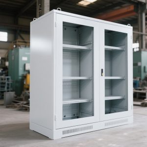
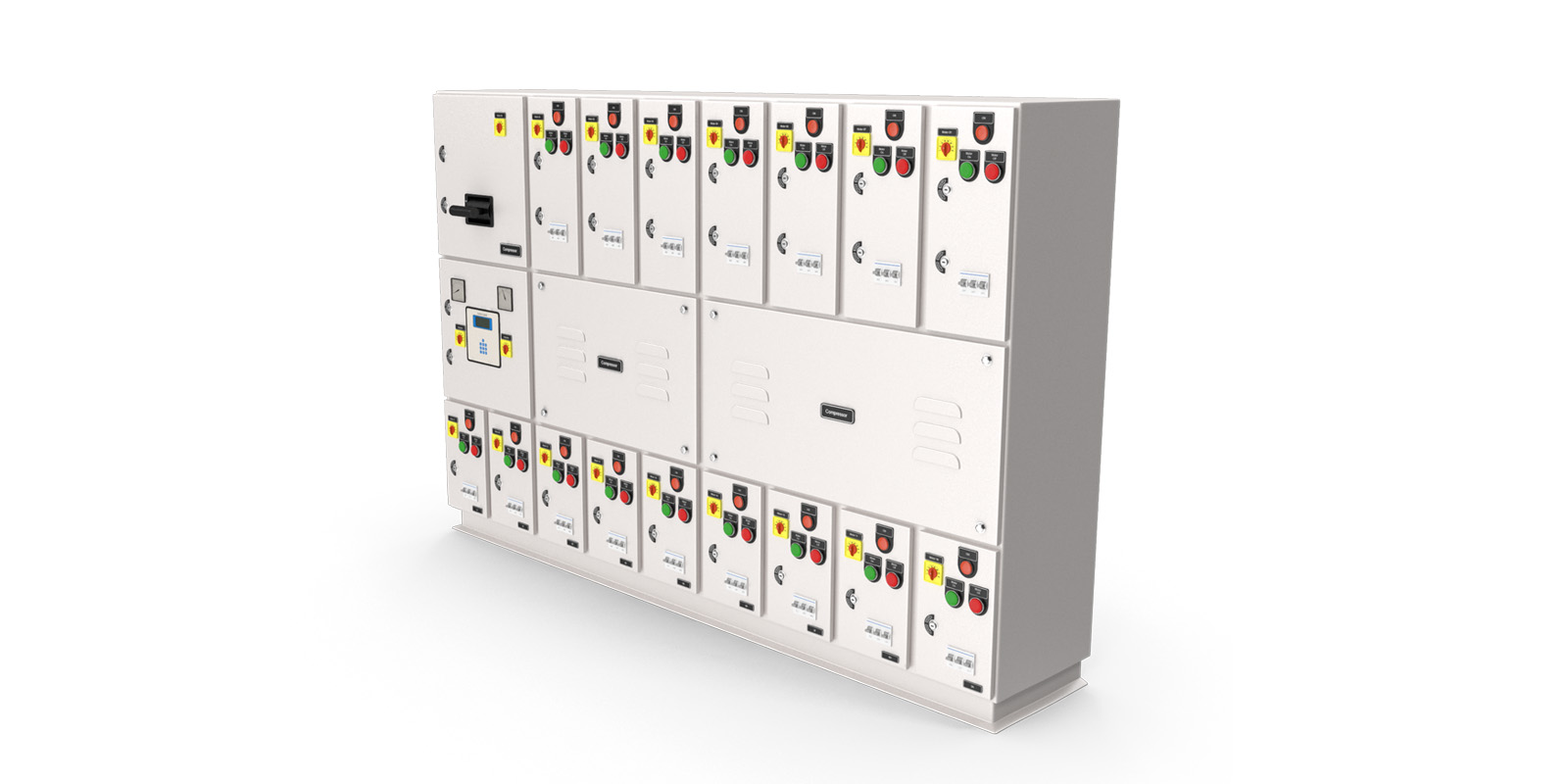
Welcome to our blog! Here, we explore “General Technical Requirements for Electrical Cabinets: Definitions and Illustrations of Mechanical Structures for Electrotechnical and Electronic Equipment.” This comprehensive guide introduces key terms and concepts across five dimensions: Orientation, Modulus, Dimensions, Space, Structural Type, and Components, all presented through an easy-to-follow table format.
As a company specializing in high-quality metal electrical enclosures, we strive to meet diverse industry needs with precision-engineered solutions. Dive in to learn more about Electrical Cabinet Specifications and their crucial role in modern equipment design.
Anstorm electrical and electronic equipment mechanical structure terminology definitions and schematic diagrams | |||
| Category | Terminology | Definition | Example |
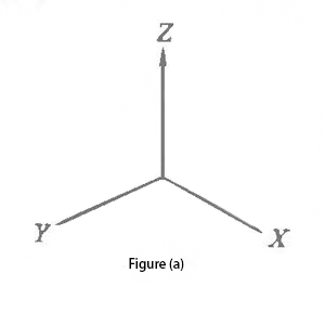
Orientation | Width | Dimensions occupied by equipment along the X-axis (front-back direction) in the three-dimensional coordinates [Fig. (a)] as shown in dimension D [Fig. (b)]. |
|
| Depth | Dimensions occupied by equipment along the Y-axis (side-to-side direction) in the three-dimensional coordinates [Fig. (a)] as indicated by dimension D [Fig. (b)]. | ||
| Height | Dimensions occupied by equipment along the Z-axis (up-down direction) in the three-dimensional coordinates [Fig. (a)] as represented by dimension H [Fig. (b)]. | ||
| Front | The primary monitoring or operating face relative to the operator, typically containing monitoring or control components [Fig. (b)]. | ||
| Rear | The face of the equipment opposite the front face [Fig. (b)]. | | |
| Left | The surface is located on the left-hand side of the operator [Fig. (b)]. | ||
| Right | The surface on the right-hand side of the operator [Fig. (b)]. | ||
| Top | The top surface of the equipment [Fig. (b)]. | ||
| Bottom | The bottom surface of the equipment. | ||
| Monitoring surface | The surface for mounting monitoring and measuring components. | ||
| Operation surface | The primary surface for installing operating components. | ||
| Horizontal surface | Surfaces parallel to sea level. | ||
| Vertical surface | Surfaces perpendicular to the horizontal plane. | ||
| Slant surface | Surfaces at an inclination concerning horizontal or vertical planes. | ||
| Reference surface | Theoretical planes are used for defining geometric spatial elements. | ||
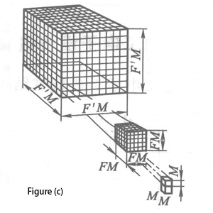
Modulus | Module | A three-dimensional structure where all edges are integer multiples of a grid interval applies to two-dimensional grids [Fig. (c)]. |
|
| Modulus | The value of a one-dimensional modular grid interval. | ||
| Basic modulus | The specified module is in a modular sequence, with its value equal to the basic grid interval. | ||
| Modulus sequence | A set of rules establishing the relationship between coordination dimensions, base grid intervals, multiple grid intervals, and installation intervals for constructing equipment. | ||
| Multiplier | Positive integers are chosen to derive modular dimensions when multiplied by the module. | ||
| Modulus size | Positive integers are chosen to derive modular dimensions through multiplication by the module. | ||
| Digital size series | A dimensional series derived from the module and a sequence of selected multipliers. | ||
| Grid | An orthogonal arrangement of lines of equal dimensions [Fig. (d)]. | 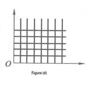 | |
| Modulus grid | Two-dimensional or three-dimensional modular grid arrangements conforming to modular series [Fig. (a) and Fig. (e)]. | 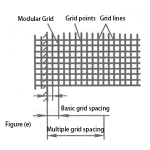 | |
| Grid lines | Lines constituting a modular grid [Fig. (e)]. |
| |
| Grid points | Intersection points of modular grid lines [Fig. (e)]. | ||
| Basic grid spacing (p) | The minimum distance between adjacent grid lines in an equipment structure. | ||
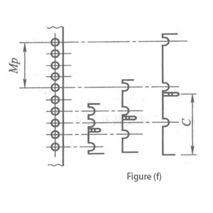
| Multiple grid spacing (Mp) | Integer multiples of the base grid interval [Fig. (f) marked as Mp]. | ||
| Mounting grid spacing | Grid spacing is used to arrange or install components within a given space [Fig. (f) marked as C]. | ||
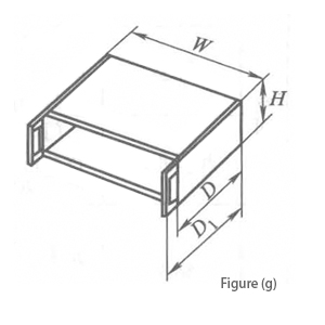
Dimensions | Overall dimensions | Maximum dimensions occupied by the equipment along the X, Y, and Z axes [Fig. (g)]. |
|
| Nominal dimensions | Overall dimensions occupied by the primary shape of the equipment along X, Y, and Z axes excluding protrusions [Fig. (g)]. | ||
| Effective dimensions of the mounting surface | Plane surface area available for component installation. | ||
| Effective dimensions of mounting space | Available space within the equipment structure for component mounting. |
| |
| Maintenance space dimensions | Movement space required for personnel or tools within the equipment for maintenance and repair. | ||
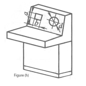
| Opening Dimensions | Dimensions of openings on panels or doors for component installation [Fig. (h) a, b, d, etc.]. | ||
| Coordination dimensions | Reference dimensions for coordinating mechanical interfaces (not manufacturing dimensions). | ||
| Plug-in panel installation dimensions | Dimensional positions for panel mounting onto racks or cabinets [Fig. (i) marked as W0]. | 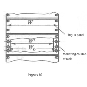
| |
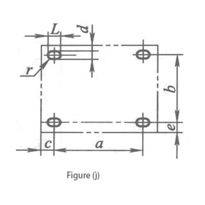
| Equipment installation dimensions | Positions and geometric dimensions of equipment mounting holes [Fig. (j)]. | ||
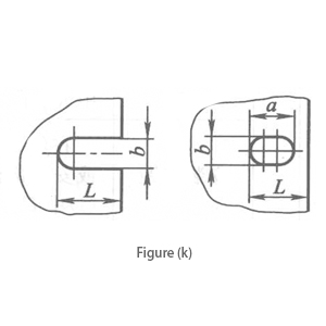
| Plug-in panel slot or mounting hole dimensions | Geometric dimensions of slots or holes on racks or cabinets for panel installation [Fig. (k)]. | ||
| Interface dimensions | Fit dimensions for junctions between components or equipment. | ||
Space | Compartment | Enclosures are typically closed unless opened for internal wiring, operation, maintenance, or ventilation [Fig. (a)]. | |
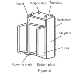
| Opening angle | Maximum rotational angle of hinged parts like doors, frames, or covers [Fig. (x)]. | ||
Structural type | Structure | The sum of interactions and connections between all parts, materials, and components of the product. | |
| Structural type | A classification method expressing basic structural characteristics. | ||
| Fixed structure | Equipment structures with fixed installation positions. | ||
| Mobile structure | Equipment structures are capable of relocation. | ||
| Portable structure | Portable equipment structures. | ||
| Open structure | Structures without specialized enclosure protection. | ||
| Protective structure | Structures with specified enclosure protection levels. | ||
| Combined structure | Structures enabling the modular assembly of multiple units into desired equipment. | ||
| Plate structure | Main components of equipment, assembled or welded from sheet metal. | ||
| Profile structure | The main components are made from profile sections. | ||
Overall structure | Entire piece | Components with a complete, independent structure or function, possibly assembled from smaller parts. | |
| Equipment structure | Mechanical structures accommodate electrical or electronic systems and ensure compatibility among components. | ||
| Rack | Enclosure-less structures for housing electrical or electronic equipment [Fig. (i)]. | 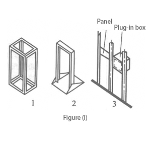 | |
| Rack row | Series of parallel-mounted racks of similar height and depth [Fig. (m)]. | 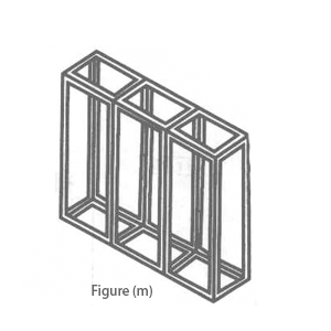 | |
| Chassis | Special mechanical structures supporting electrical and electronic components [Fig. (n)]. | 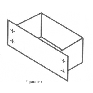 | |
| Screen | Racks with fixed panels [Fig. (o)]. | 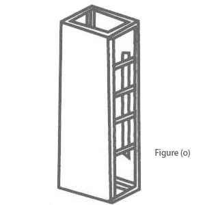 | |
| Screen row | Screens in series, often similar in height and depth [Fig. (p)]. | 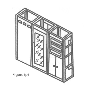 | |
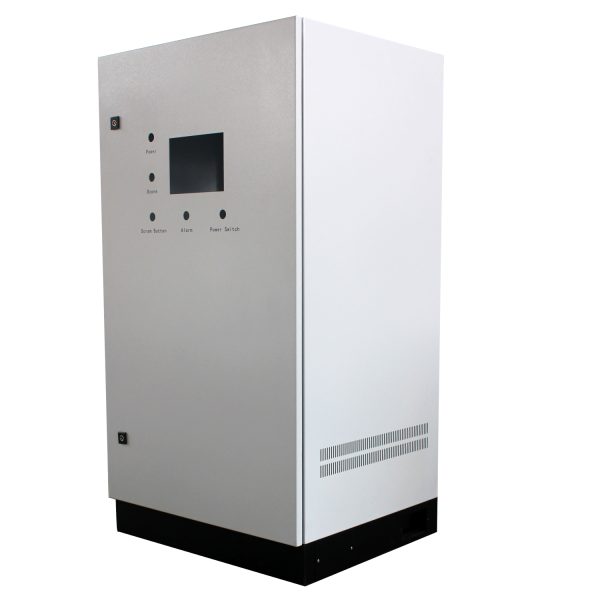
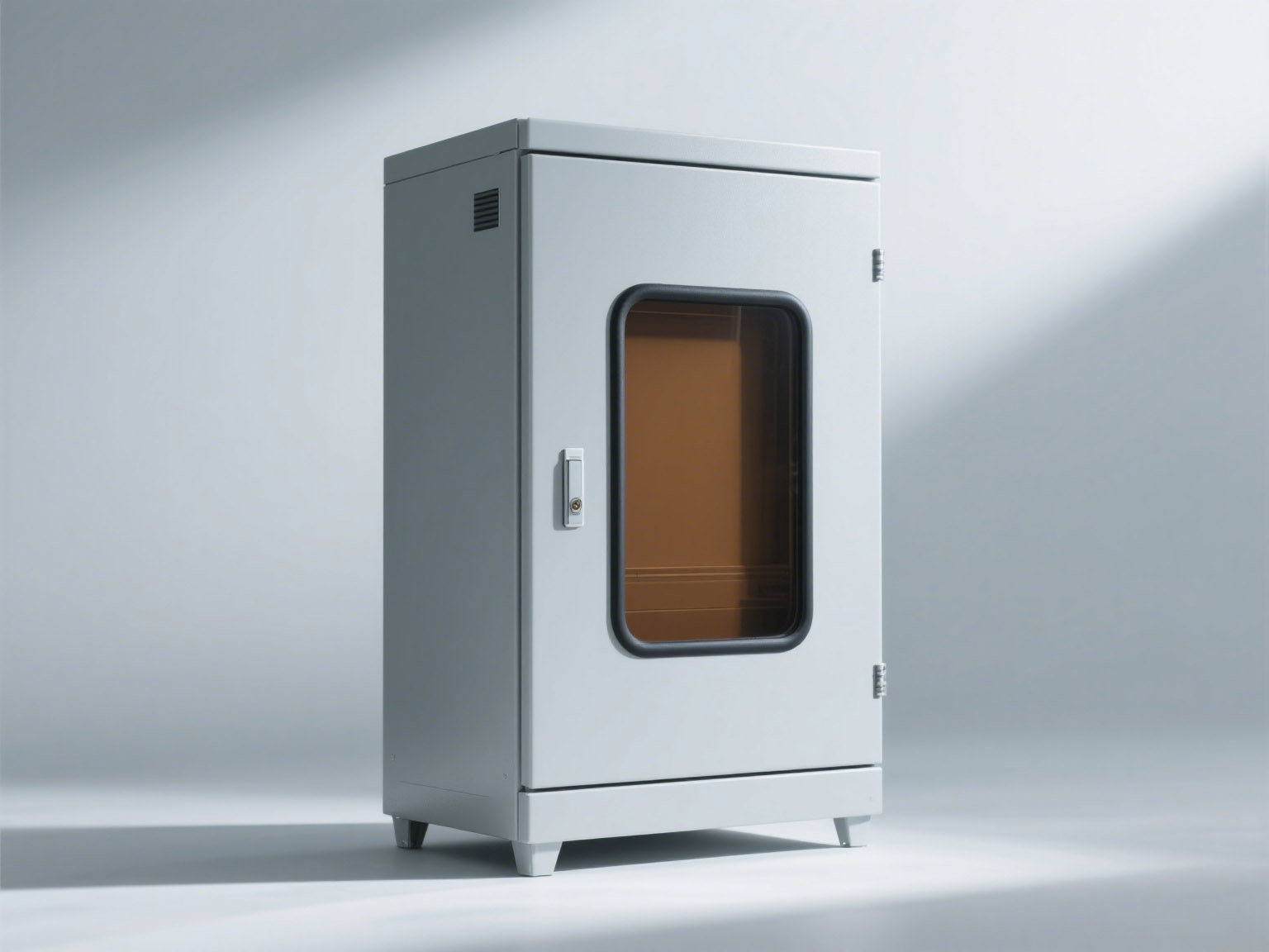
| Cabinet | Freestanding or self-supporting enclosures, often with doors and detachable panels [Fig. (q)]. | 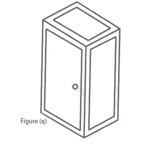 | |
| Cabinet row | Racks or cabinets arranged linearly [Fig. (r)]. | 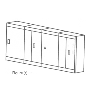 | |
| Box | Small enclosures mounted on tables, walls, or surfaces [Fig. (s)]. | 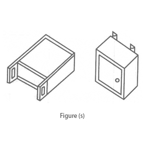 | |
| Console | Enclosures on tables or floors with horizontal, vertical, or inclined surfaces to accommodate control or monitoring devices [Fig. (t)]. | 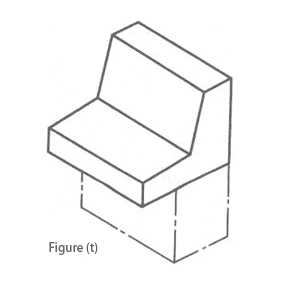 | |
| Plug-in | Units inserted into racks, supported by rails, including plug-in boards and framed or boxed units [Fig. (u)]. | 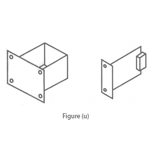 | |
| Plug-in box | Structures housing printed boards and plugins [Fig. (v)]. | 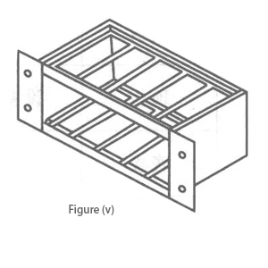 | |
Components | Component | Assembled parts forming structural elements, either detachable or integral. | |
| Part | Single-piece components without assembly. | ||
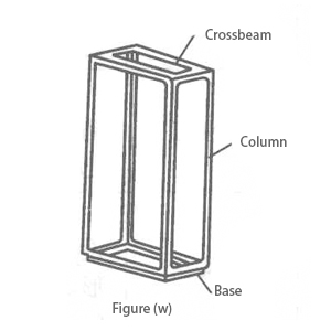
| Beam | Horizontal supports in structures [Fig. (W)]. |
| |
| Column | Vertical supports in structures [Fig. (W)]. | ||
| Base | Base supports, often frame-shaped [Fig. (W)]. | ||
| Castor | Components with wheels for equipment mobility. |
| |
| Panel | A plate is usually placed on the vertical mounting surface at the front of a rack or cabinet [Figure (X)] | ||
| Back panel | A plate was installed behind the equipment (opposite to the front) [Figure (X)].Note: A plug box, refers to the board used to interconnect the connector and the printed circuit board | ||
| Cabinet cover | A component on the outside of the cabinet is used to protect against accidental contact and environmental influences [Figure (y)]Note: Cover panels can be considered as a general term for side panels, top panels, bottom panels, etc. |
| |
| Side panel | Panels on both sides of the equipment [Figure (x)] | ||
| Top panel | Panels on the top of the equipment [Figure (x)] | ||
| Bottom panel | Panels on the bottom of the equipment [Figure (x)] | ||
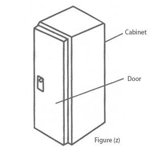
| Door | Hinged cabinet cover panels with typical latches and/or locking devices [Figure (z)] | ||
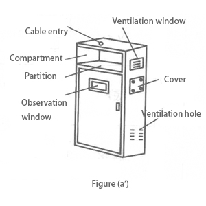
| Cover | Panels covering holes in the casing, usually fixed with screws [Figure (a’)] |
| |
| Partition | Panels that divide the internal space of the equipment structure in the vertical or horizontal direction [Figure (a’)] | ||
| Observation window | A window-type panel is used to observe the internal components of the equipment Transparent component [Figure (a’)] | ||
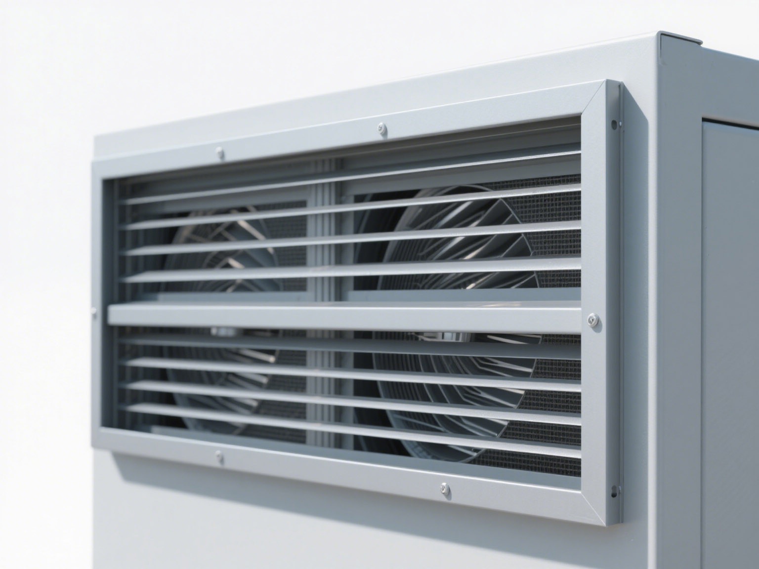
| Ventilation window | Component installed on the housing to facilitate airflow and dissipate heat inside the equipment [Figure (a’)] | ||
| Ventilation hole | Hole on the housing to facilitate airflow and dissipate heat inside the equipment, often in the shape of a circle, rectangle, or louver [Figure (a’)] | ||
| Mask | A transparent component installed in front of the equipment or plug-in box to protect and observe the internal components of the equipment | ||
| Air duct | A channel in the equipment structure that guides the airflow | ||
| Lifting ring | Component for lifting equipment [Figure (x)] | ||
| Cable inlet | A hole in the equipment housing allows the cable to pass through and enter the equipment [Figure (a’)] | ||
| Hinges | A rotatable and foldable connector [Figure (b’)] | 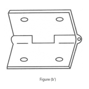 | |
| Plug-in guide rail | The plug-in box is used to guide, fix, and support the plug-in and printed components with plug-in components Components for supporting panels [Figure (c’)] | 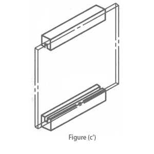 | |
| Slide rail | Components for supporting and sliding plug-in boxes and chassis in racks, cabinets, and boxes [Figure (d’)] | 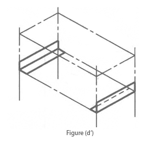 | |
| Telescopic slide rail | Components for supporting plug-in boxes and chassis that can be withdrawn and retracted in the extended position [Figure (e’)] | 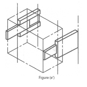 | |
| Stopper | Components for limiting the extreme positions of movable parts | ||
| Swivel frame | Hinged frame for fixing electrical and (or) electronic equipment, which can be rotated to access its back [Figure (f’)] | 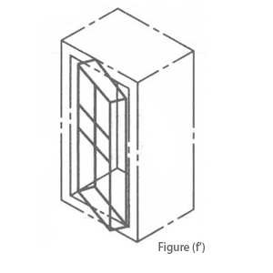 | |
| Mounting plate | A board for mounting electrical and electronic devices is placed in the cabinet [Figure (g’)] | 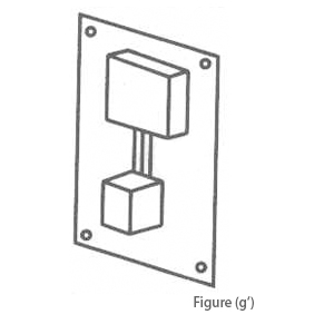 | |
| Mounting frame | Frame structure for mounting electrical and electronic devices, which can be fixed or moved in the cabinet [Figure (h’)] | 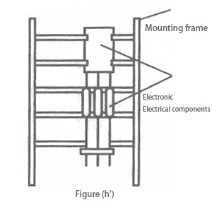 | |
| Mounting bar | Strip parts for mounting components, devices, and parts [Figure (i’)] | 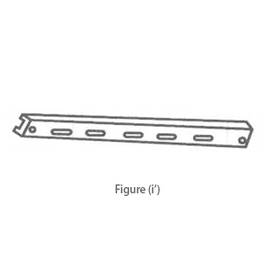 | |
| Mounting rail | Guide-type parts for quickly mounting components and devices [Figure (j’)] | 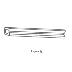 | |
| Bus duct | Support busbars and prevent contact with busbars Components for clamping and supporting busbars [Figure (k’)] | 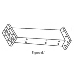 | |
| Bus clamp | Insulating components for clamping and supporting busbars [Figure (l’)] | 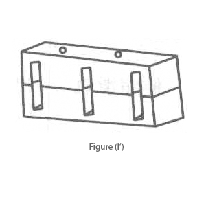 | |
| Wire clamp | Components for clamping and supporting conductors [Figure (m’)] | 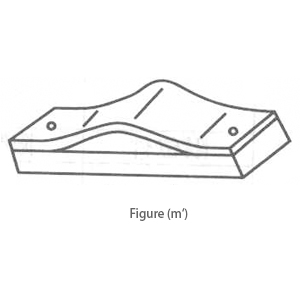 | |
| Wire duct | A trough-shaped component for laying conductors or cables, usually with a cover [Figure (n’)] | 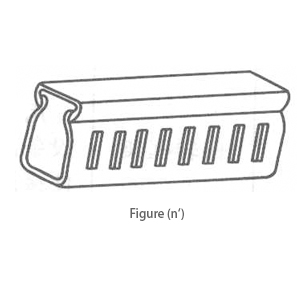 | |
| Sealing gasket | An elastic component that acts as a seal at the joint of the components | ||
| Plug and puller | A mechanism that facilitates the insertion and removal of the plug-in unit, which may have a locking function [Figure (o’)] | 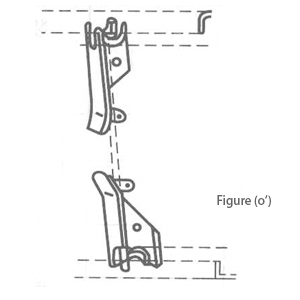 | |
| Handle | Components installed on the door for opening and closing the door [Figure (p’)] | 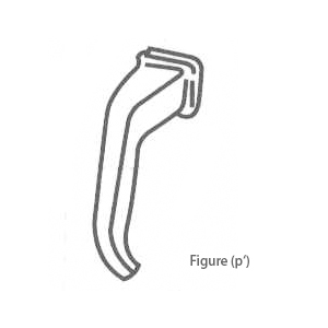 | |
| Handle | Components installed on the chassis for carrying | ||
| Handle | Components installed on the plug-in unit or plug-in box, mainly for horizontal pulling [Figure (q’)] | 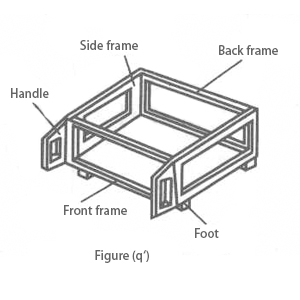 | |
| Foot | Components that support the casing and prevent it from directly contacting the mounting surface [Figure (q’)] | ||
| Support foot | A support installed on the bottom of the box to make the box tilted [Figure (r’)] | 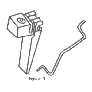 | |
| Lock | It is installed on the door and plug-in unit of the equipment and requires the use of special tools (key) | ||
| Locking piece | A device installed on the door and insertion unit of the equipment, which can be opened without the help of special tools | ||
| Fence | A component that protects against direct contact from any direction of frequent approach | ||
| Shielding cover | A non-fully enclosed component that isolates or weakens the influence of electric, magnetic, or electromagnetic fields [Figure (s’)] | 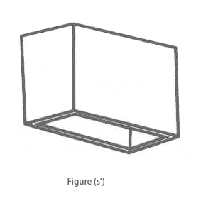 | |
| Shielding box | A fully enclosed component that isolates or weakens the influence of electric, magnetic, or electromagnetic fields [Figure (t’)] | 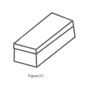 | |
| Shielding plate | A plate-shaped component that isolates or weakens the influence of electric, magnetic, or electromagnetic fields | ||
| Shielding net | A mesh component that isolates or weakens the influence of electric, magnetic, or electromagnetic fields [Figure (u’)] | 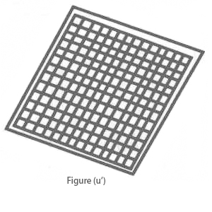 | |
| Vibration absorber | Elastic components that reduce the influence of vibration on equipment or components [Figure (v’)] | 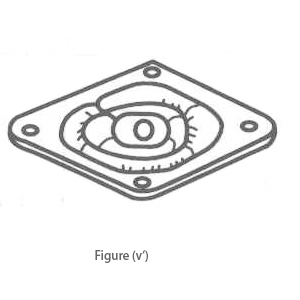 | |
| Radiator | Parts that increase the heat dissipation area of components and accelerate heat dissipation [Figure (w’)] | 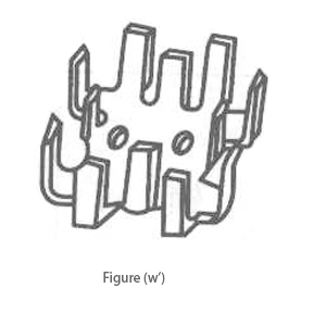 | |