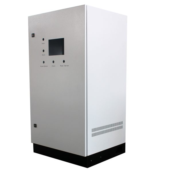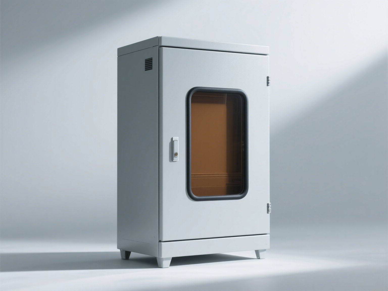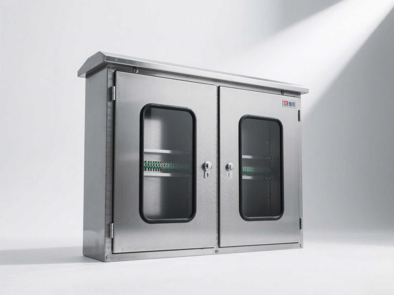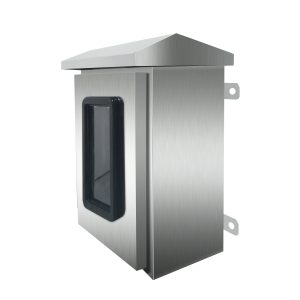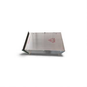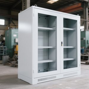
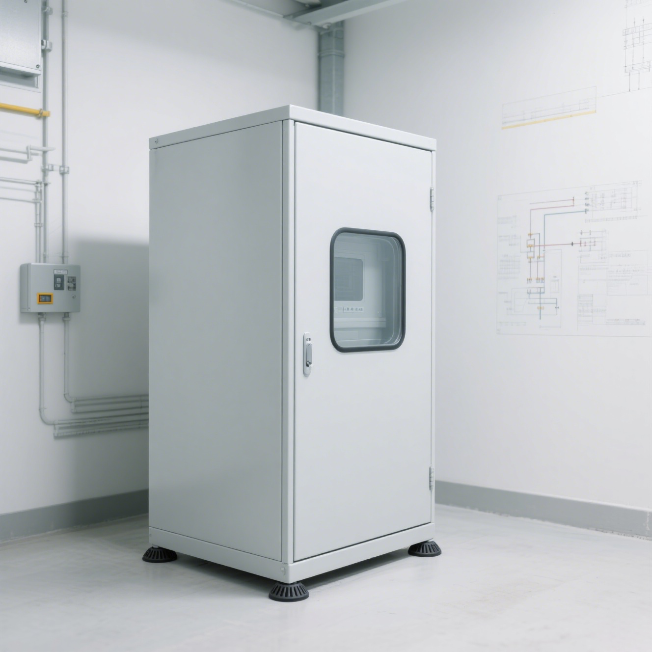
Steel control cabinet assembly requirements should be defined in the drawing, BOM and inspection plan—not left for decisions on the production floor. A repeatable assembly process improves fit, service access and traceability while reducing rework caused by incompatible hardware or inaccessible fasteners.
Confirm the Approved Drawing and BOM
Before assembly, verify the drawing revision, material, finish, part quantities and purchased hardware. Doors, mounting plates, bases, locks, hinges, seals and cable-entry parts should match the approved configuration. Substitutions should be documented and reviewed before they are installed.
Build and Check the Frame or Main Body
For welded cabinets, inspect joint location, distortion and critical dimensions before finishing. For assembled or modular cabinets, confirm member orientation, fastener type and tightening method. Check squareness, level contact surfaces and mounting interfaces before adding doors or internal equipment.
Install Doors, Panels and Removable Parts
Doors should open through the required angle without interference and maintain consistent gaps. Locks, hinges, stays and removable panels must be accessible with the intended tools. Captive or retained hardware may be specified where loose fasteners would create a service risk. Gaskets should be continuous, correctly joined and compressed by the intended closing hardware.
Mount Plates, Rails and Internal Supports
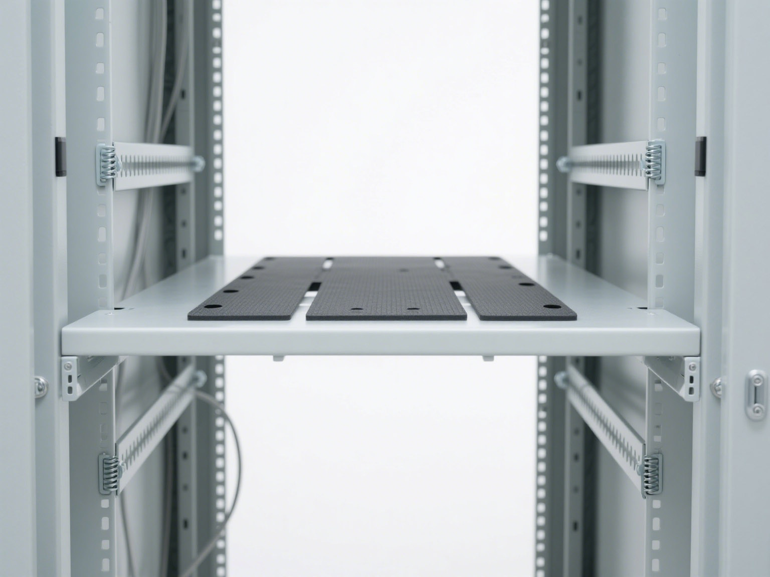
Locate mounting plates, rails, ducts and brackets from controlled datums. Verify that fasteners do not obstruct cable routes or equipment installation. Heavy components may require local reinforcement or additional support; their mass and center of gravity should be considered before finalizing the internal layout.
Plan Bonding and Wiring Access
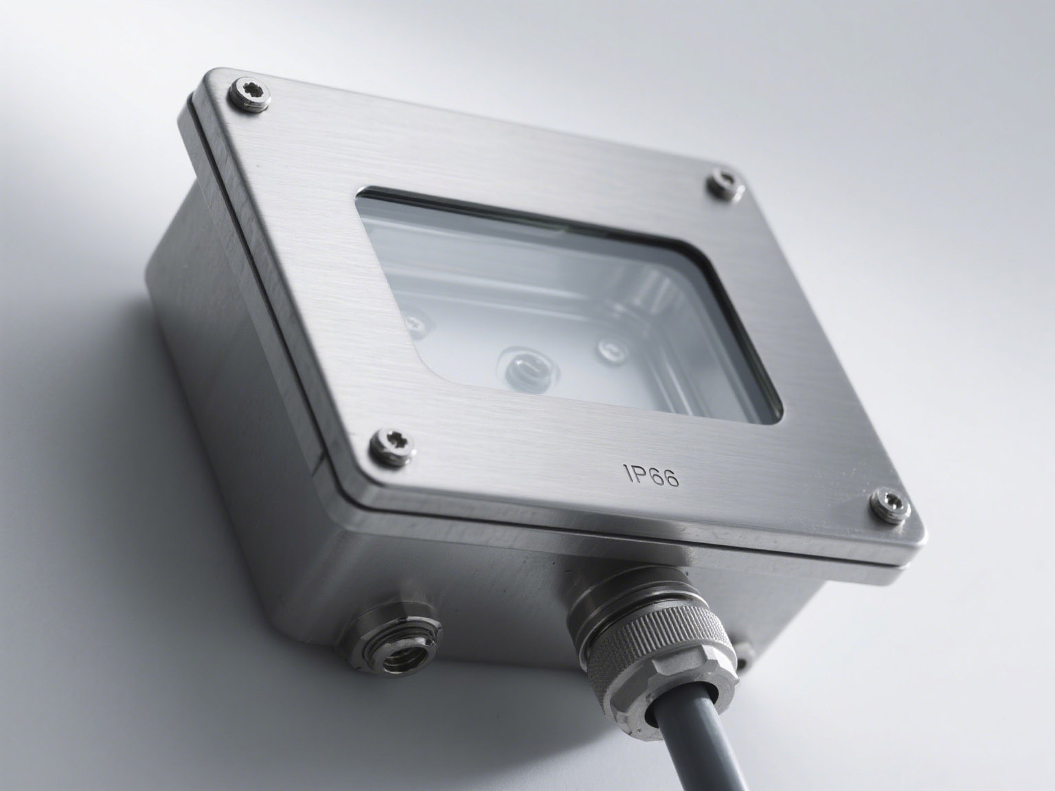
Provide defined bonding points for the main body, doors and removable panels. Coating must not prevent the intended conductive contact. Cable entries, terminal access, wiring ducts and bend radii should be checked with the actual or representative components. Keep power and signal routes separated where the electrical design requires it.
Make Maintenance Possible
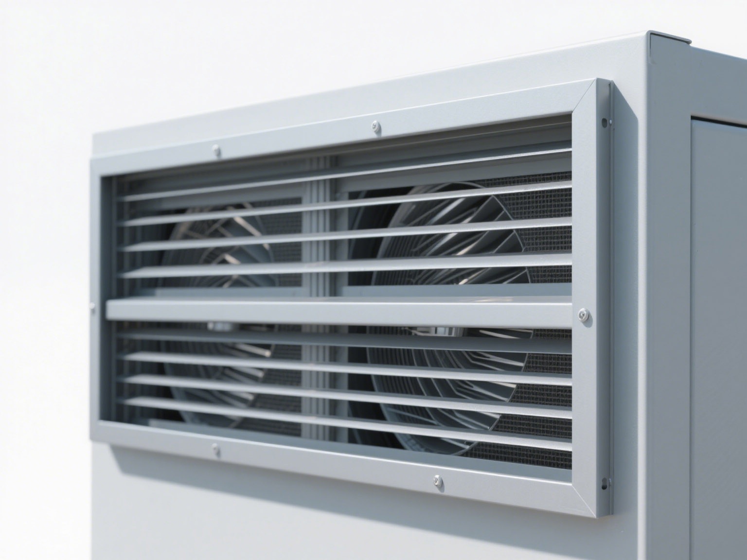
Technicians should be able to inspect, tighten or replace serviceable parts without unnecessary dismantling. Check tool clearance around locks, terminals, fans and mounting hardware. Modules intended for replacement should have documented interfaces and enough space for removal.
Final Mechanical Inspection
- Overall dimensions, squareness and mounting interfaces
- Door alignment, lock operation and panel removal
- Specified fasteners, retention and visible damage
- Mounting plate and accessory positions
- Gasket continuity and cable-entry preparation
- Bonding provisions and marked grounding points
- Finish, labels and drawing/BOM revision
The acceptance plan should distinguish enclosure fabrication checks from electrical tests performed on the completed system. See the quality inspection process and electrical control cabinet range. Send the drawing and BOM through the contact page for a quotation review.