
Design Considerations for Electronic Equipment Enclosures, Plug-in Boxes
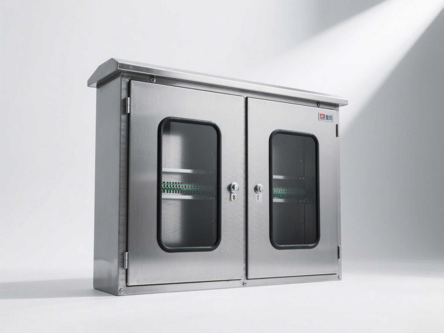
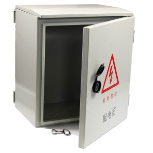
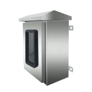
Electronic enclosures, plug-in boxes, and modular panels are essential in equipment design. Their dimensions must align with standardized series for compatibility and flexibility.
Panel Heights and Widths:
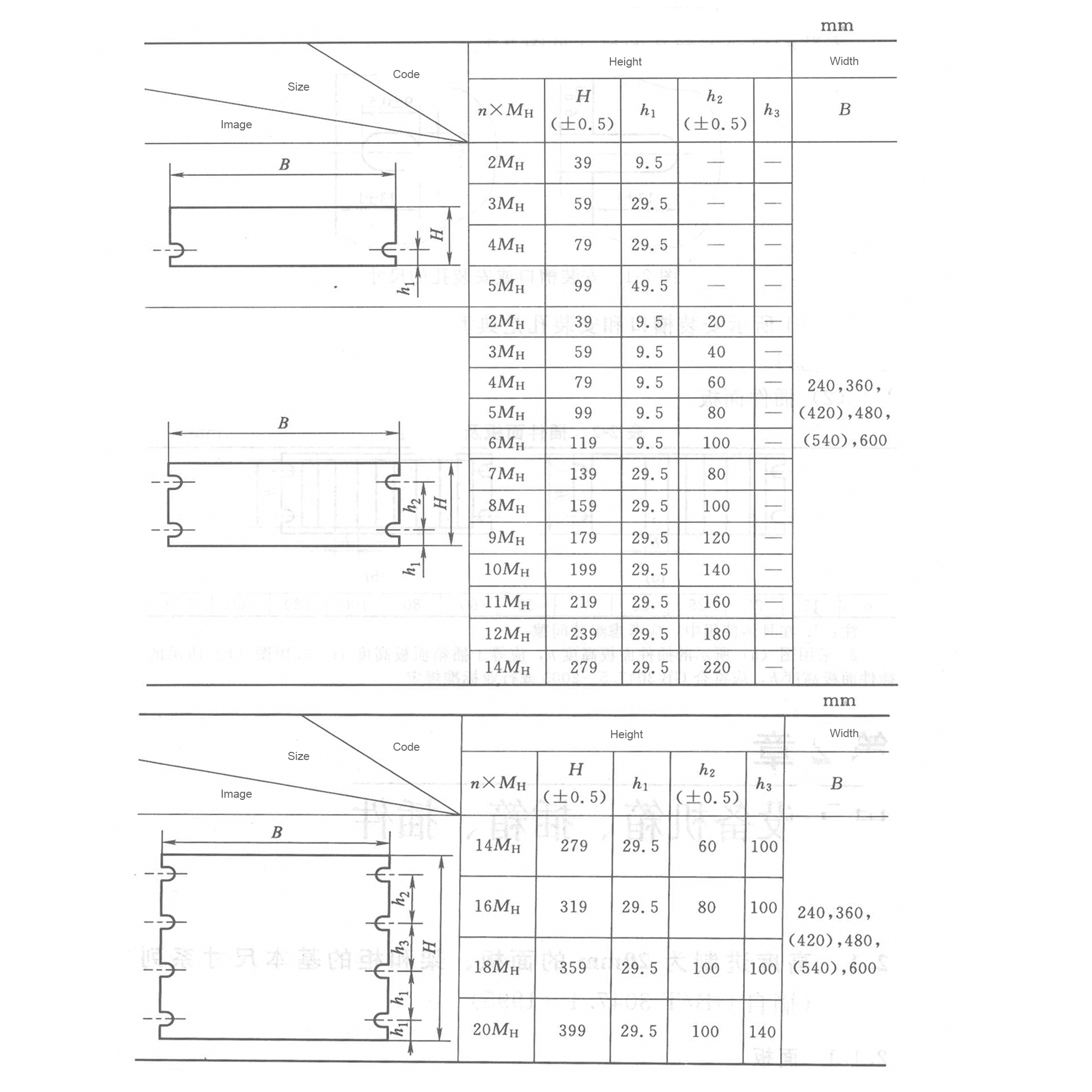
Panels follow modular standards, typically in 20 mm increments.
Plug-in panel and its height and width
Slot and Hole Configurations:
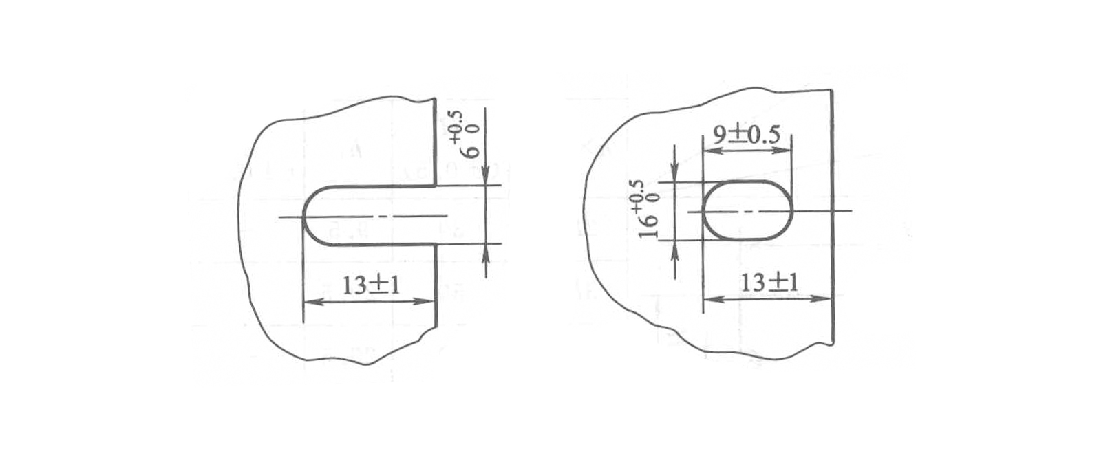
Mounting slots and holes are crucial for secure assembly. While typical configurations exist, customization based on specific equipment needs is possible.
Dimensions of mounting notches or holes
Plugin Panel Dimensions:
Plug-in panel dimensions must accommodate assembly gaps and adhere to standards, ensuring compatibility across various applications.
Plugin panel and its width

Standardized designs not only enhance assembly efficiency but also promote interchangeability in modern equipment systems. For customized solutions, adapting dimensions to project needs is vital.
Begin With the Module and Rack Interface
Define panel height, width, insertion direction and the rack or subrack interface. Standard increments can support interchangeability, but the applicable series and tolerances must be named in the drawing.
Allow for Assembly and Removal
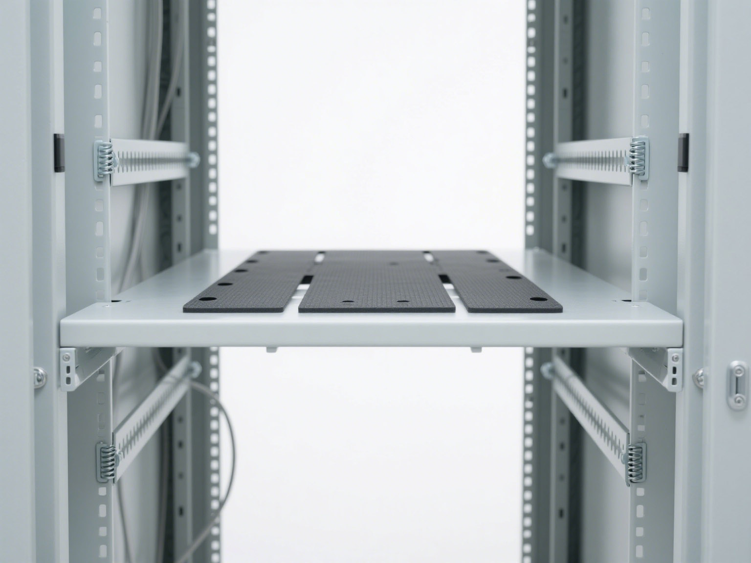
Provide clearance for guides, connectors, handles, fasteners and card extraction. Tolerances should prevent interference without creating excessive movement.
Coordinate Slots and Mounting Holes
Hole patterns need controlled datums. Confirm edge distances, hardware, thread requirements and whether panels must be replaceable between positions.
Plan Cooling and Cable Access
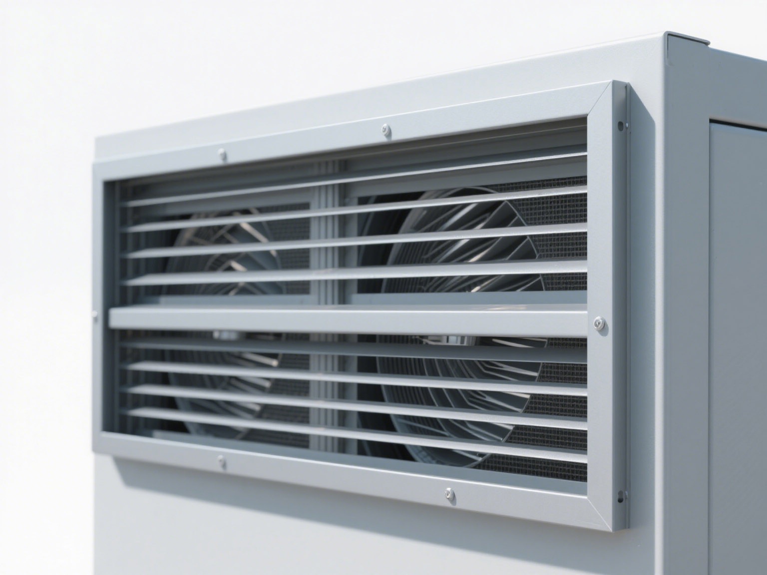
Heat load, airflow direction and connector space affect panel layout. Vent openings can influence shielding and protection, so thermal and EMC requirements should be reviewed together.
Control the Drawing Package
Release panel, rack and interface drawings under the same revision. Include materials, finishes, quantities and inspection dimensions.
Compare the 19-inch rack guide and custom PCB enclosures. Send the interface drawing through the contact page.
Prototype and First-Off Verification
For a new interface, inspect a first-off panel with representative hardware before releasing the batch. Check insertion, extraction, connector alignment, fastener access and visible gaps against the controlled drawing.
Keep the approved interface dimensions available for replacement modules so later equipment can be checked before manufacture.