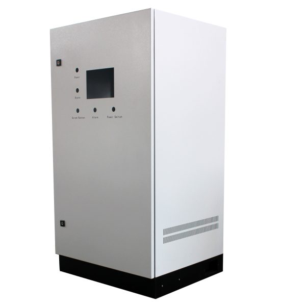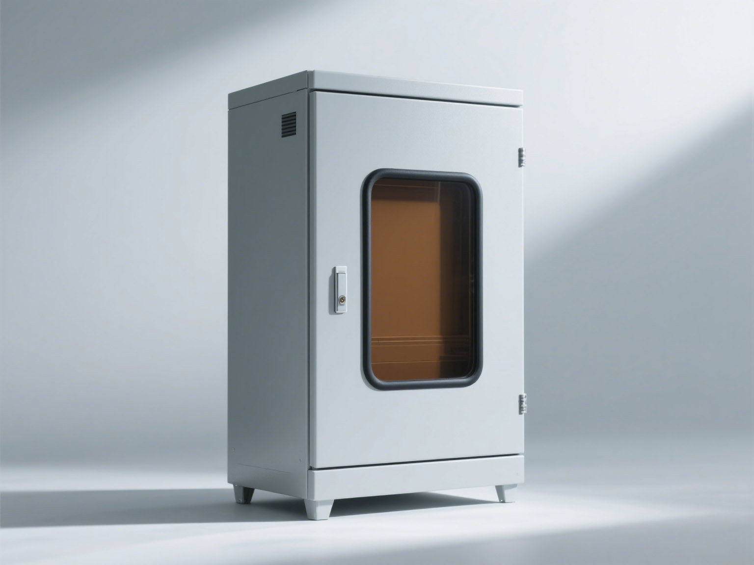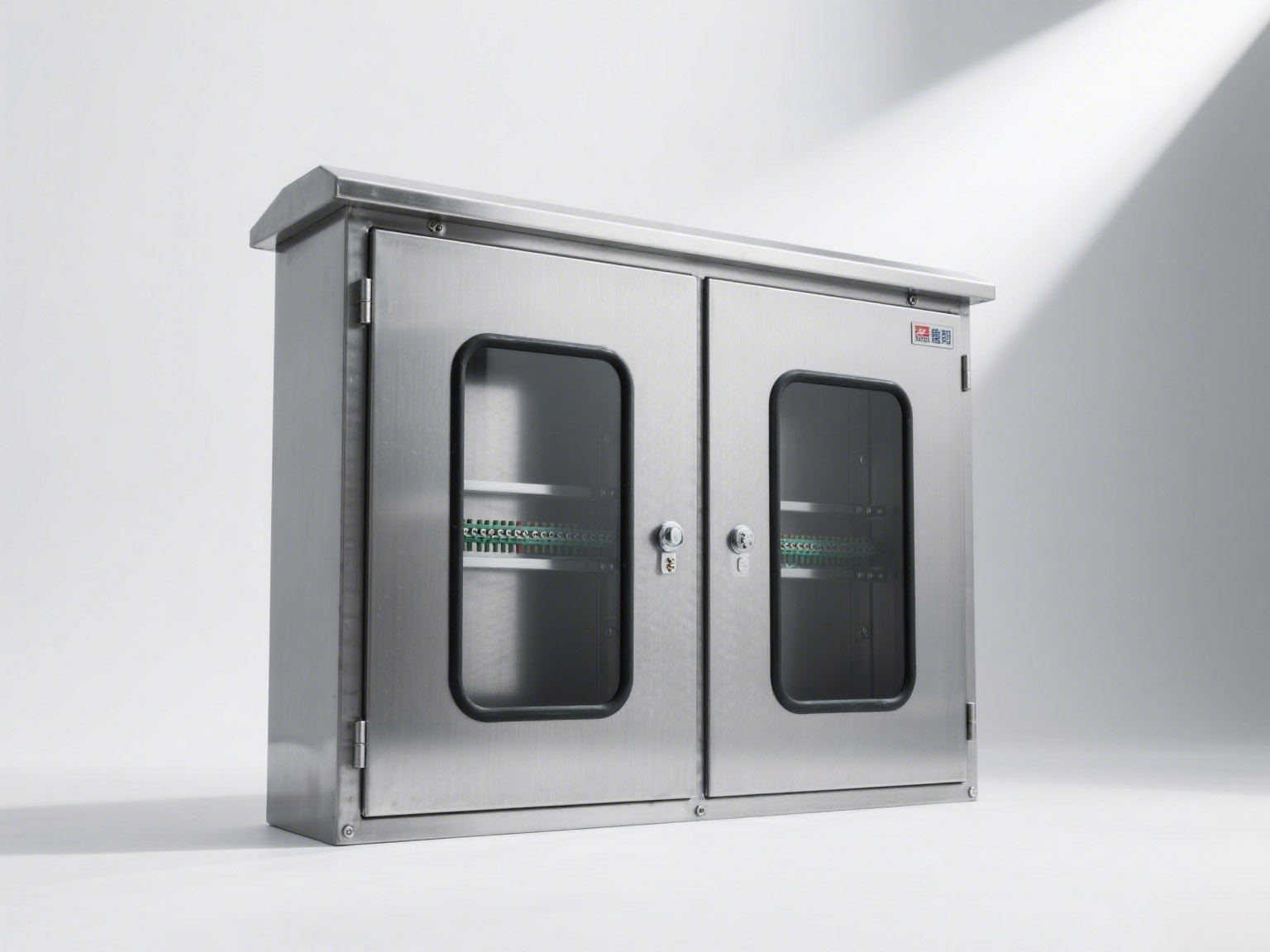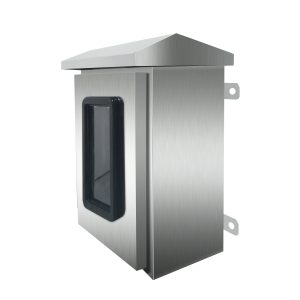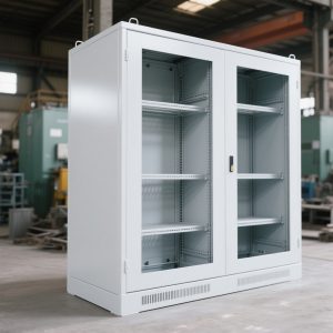

The overall configuration design is expressed in the form of the general assembly diagram and the general wiring diagram of the electrical system. The diagram should reflect the location of the main components of each part and the wiring relationship of each part, the wiring method, and the wiring troughs and pipelines used in a schematic form.
1. Division of electrical control cabinet components
The overall configuration design task of the electrical control cabinet is to divide the control system into several components (these components are called components) according to the working principle and control requirements of the electrical schematic diagram, and then divide each component into several components according to the complexity of the electrical control cabinet.
Due to the different installation positions of various electrical components, components must be divided when forming a complete electrical control system.
For some commonly used components, relatively mature modules have now been formed. These modules have reasonable structures, reliable operation, and have been tested for a long time. These mature modules should be used first in the design of electrical component layout drawings, which can effectively improve the design efficiency, facilitate the standardization of design work, can greatly reduce production and manufacturing costs and improve product reliability.
1) Principles of component division
(I) Group components with similar functions and installation methods together;
(2) Reduce the number of connections between components as much as possible, and place control appliances with close wiring relationships in the same component;
(3) Separate strong and weak current controllers to reduce interference;
(4) To strive for neatness and beauty, appliances with similar dimensions and weights can be grouped;
(5) In order to facilitate inspection and debugging of electrical control systems, components that require frequent adjustment, and maintenance and are easily damaged should be grouped together.
2) Common methods of dividing components of electrical control equipment
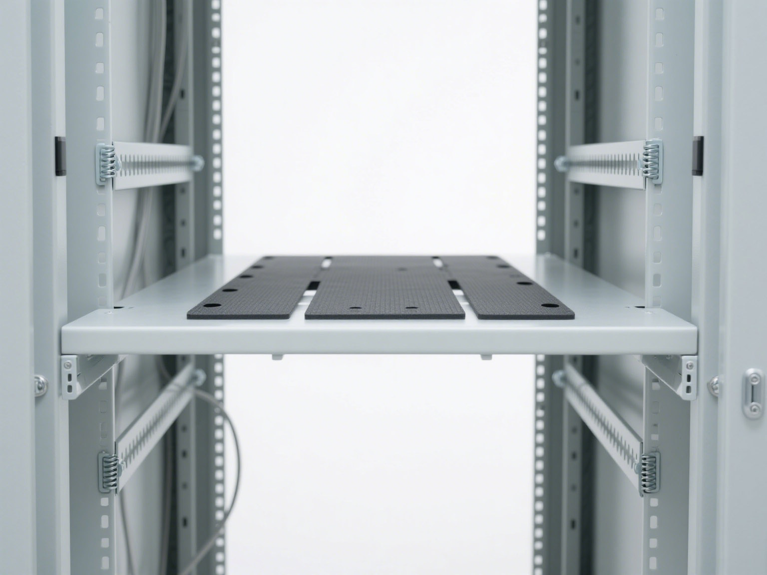
For electrical control systems with a small control scale, the electrical components of the primary circuit and the main circuit are large in size and weight, are generally installed in a frame-type manner, and are usually treated as a part. The electrical components of the secondary circuit and the control circuit are small in size and weight, are generally installed on a mounting plate, and are usually treated as a part.
Drawer-type installation and plug-in weak current installation boards generally treat them as a part. This division method is conducive to meeting the design standard requirements of wiring, and the location of electrical components is easy to determine.
For example, the main function of the primary circuit (main circuit) in electrical control equipment is mostly to control the on and off of the power supply of the controlled object, which requires the use of switching electrical appliances. There are already mature modules for switch control components. For large current circuit switch control components, the module of isolating switch plus load switch is generally used. For another example, the main circuit of motor control has formed a mature module of circuit breaker → fuse → AC contactor → thermal relay. Its layout is generally arranged from top to bottom, and the middle phase is required to be on an axis to facilitate the processing and installation of the busbar.
According to the standards and specifications for the installation and wiring of components in the electrical control cabinet, first determine the position of each component on the frame, and then determine the position of each component on the mounting plate to determine the size and installation method of the mounting plate. Then, according to the wiring relationship of the electrical schematic diagram, sort out the input and output line numbers of each part, and adjust the connection method between them. This design work is a process that needs to be repeated many times. It is necessary to change the position of components on the CAD assembly drawing many times for trial assembly until the design standard requirements are met and the designer is satisfied.
2. The impact of wiring scheme on component layout design
(1) Propose the basic wiring form of the primary side (or high-voltage side) and secondary side of the control device.
(2) Select the connection method of the power supply. Including access point, voltage level, power supply method, etc.
(3) Determine the routing method:
Determine whether the routing method is busbar connection, wire trough routing, wire harness routing, front-of-board routing, or back-of-board routing. Different routing methods have a great impact on the layout design. For example, if the primary circuit must use a busbar connection, the busbar is thick and hard, and the bending process is difficult, the layout of the primary circuit control electrical appliances must consider the feasibility of busbar processing and installation.
(4) Comprehensively organize the above-mentioned partial schemes and preliminarily propose several technically feasible wiring schemes, with the principle of not omitting the best scheme. Then combine the actual situation of the control equipment for technical analysis and comparison, and select 2~3 better schemes.
(5) According to the specific situation of the control equipment and the basic requirements of wiring, a technically reasonable wiring scheme should be selected, and the access point, number of outgoing line loops and outgoing line voltage level should be indicated on the electrical component layout diagram accordingly.
3. Principles to be followed in wiring methods
The wiring methods between the various parts and components of the electrical control cabinet should generally follow the following principles:
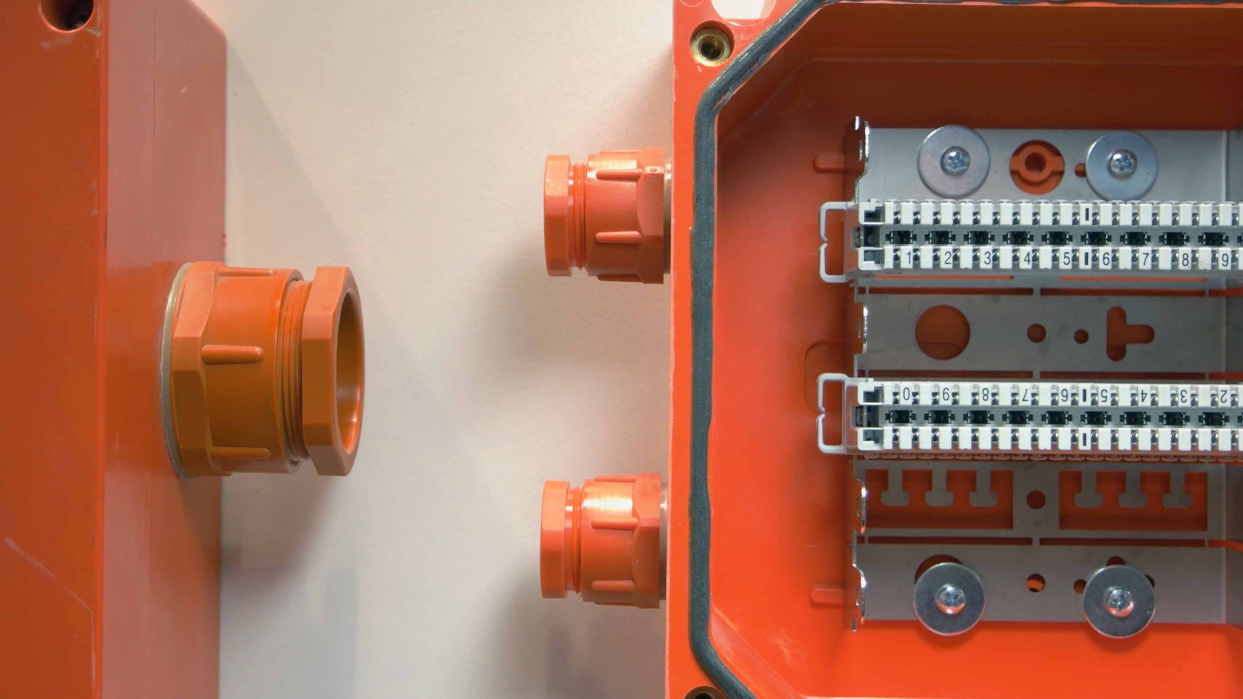
(I) The incoming and outgoing lines of large-current switching devices the large-current control cabinet and the controlled equipment are generally connected by bus terminals or wiring noses. Different specifications of wiring terminals or wiring noses can be selected according to the current size and the number of incoming and outgoing lines.
(2) The connection between control cabinets, cabinets (stations), and between them, and control circuits are generally connected by terminal blocks or industrial connectors.
(3) Various types of standard connectors should be used to connect weak-current control components and printed circuit board components.
(4) The connection between components in electrical cabinets, control cabinets, and cabinets (stations) can also be made directly using the wiring terminals of the components themselves. Transition connecting wires should be connected using terminal blocks, and the ends should be processed with wiring terminals of corresponding specifications.