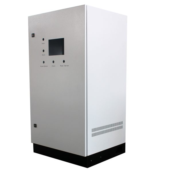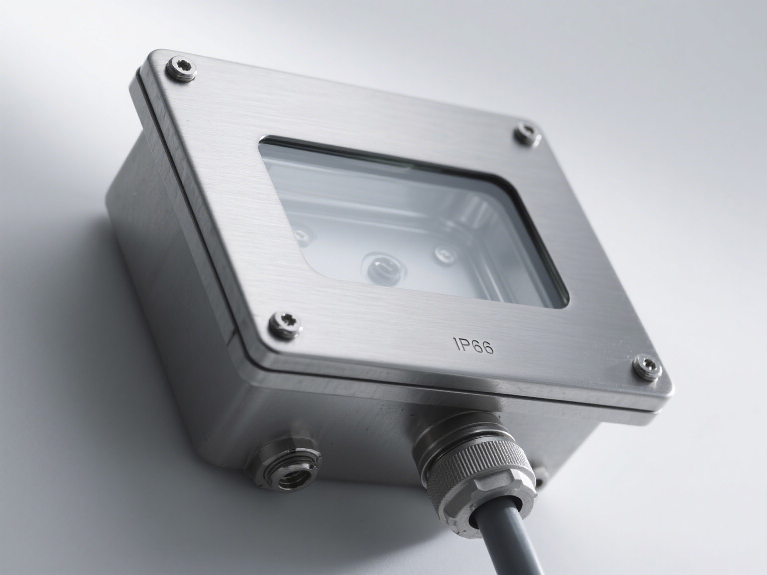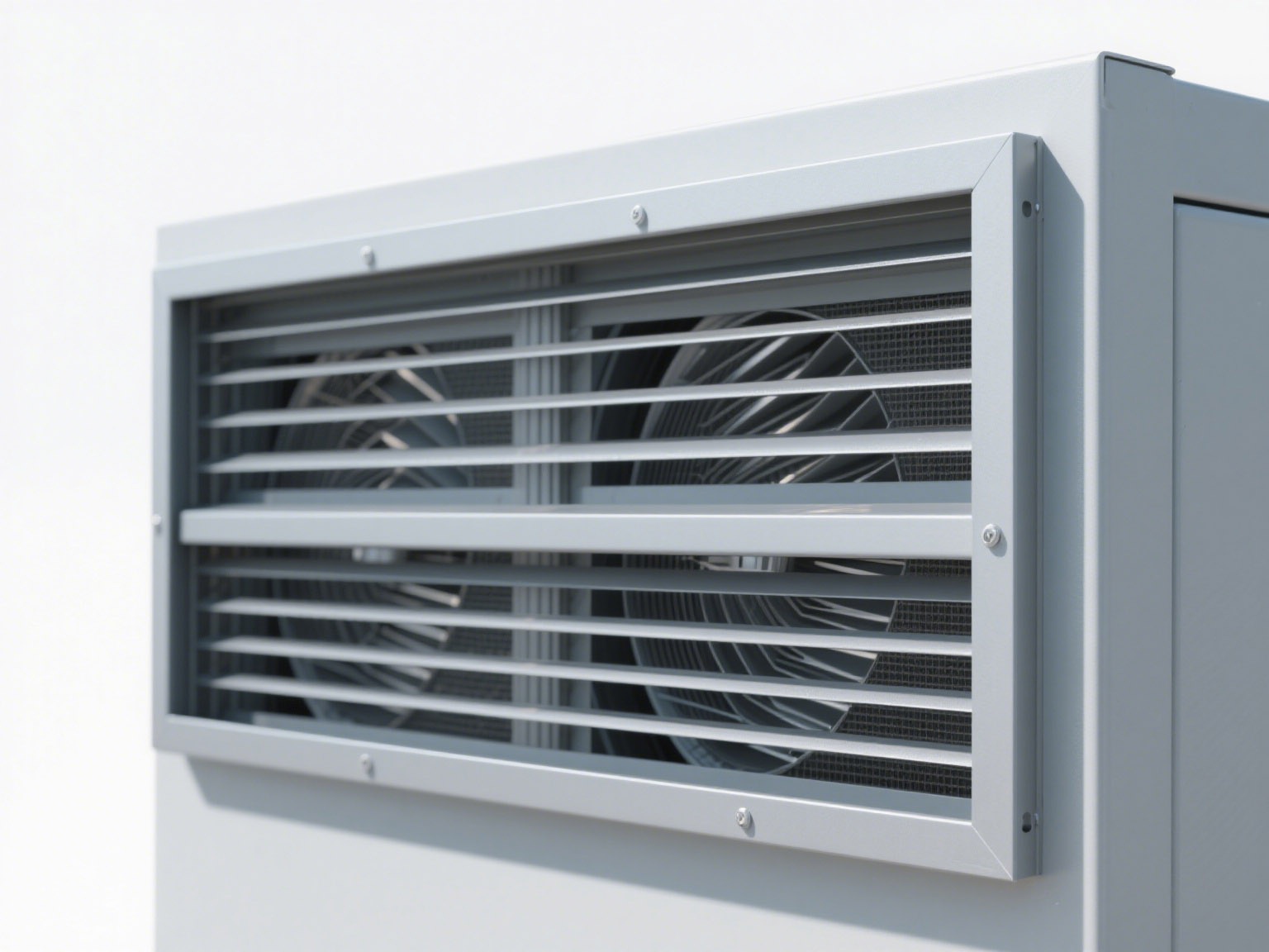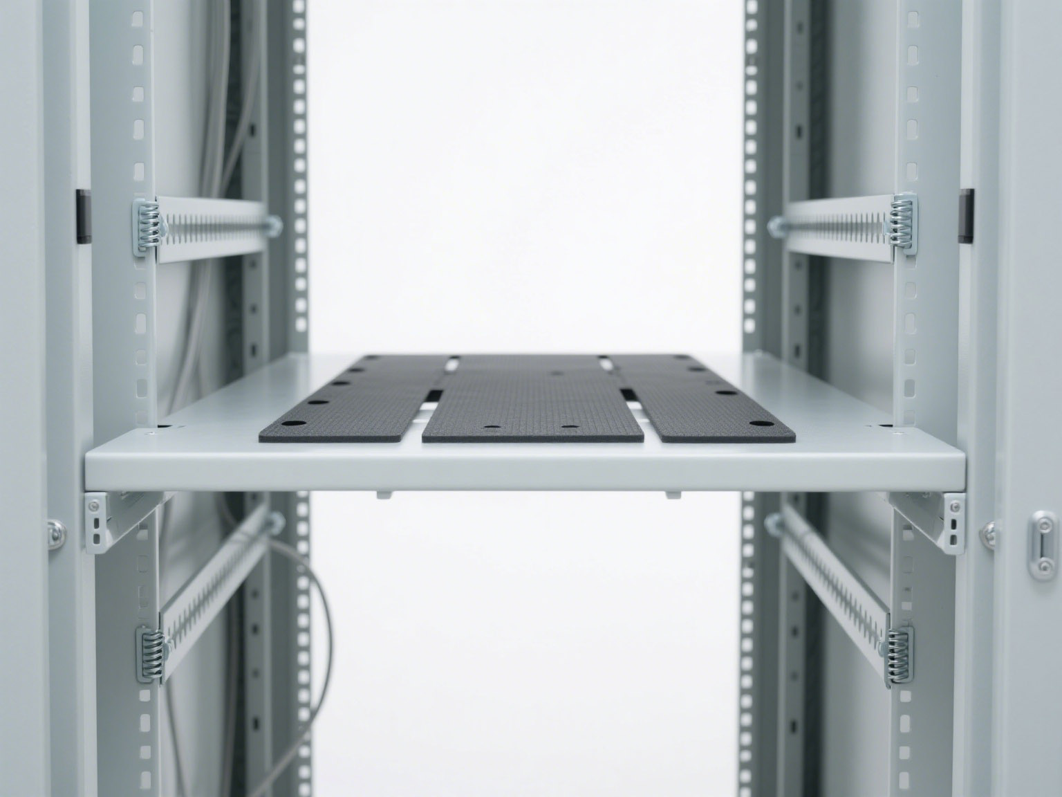
In designing and making electrical control cabinets, the electrical system plays a key role in shaping the structure. Electrical design decides how the components are laid out, how the current flows, how to handle overload protection, and how to allow user changes. At the same time, we need to think about environmental protection and how the structure may need to change depending on the user’s working environment. Electrical rules related to cabinet structure cover safety for people and equipment, as well as safe distances between wires and surfaces. Let’s look at how electrical design affects cabinet structure in detail.
1. Main Wiring Plan: The ‘Planner’of Internal Layout
Each type of electrical control cabinet comes with an installation guide that includes a table of main wiring plans and their codes. Users pick the right wiring plan based on how power enters and exits the cabinet. They combine these options to create the main circuit diagram and layout.
We usually group main wiring plans into cable inlet/outlet units, left-right connection units, control units, and protection units. The main wiring plan sets the layout inside the cabinet, so it’s a key part of cabinet design.
2. Common Busbar Systems: The ‘Limits’ of Structure
Busbars are large and hard to bend, so they don’t allow much design freedom. That’s why the layout of the control cabinet often depends on the type of busbar system. Common types include:
- Single Busbar System: Simple, low-cost, and easy to operate. But if the busbar or its switch breaks, the whole system must shut down. If one breaker fails, only that part shuts down, so power supply is less reliable.
- Single Busbar with Sections: Keeps things simple and affordable, but adds reliability. If one section fails, the rest still works. This is helpful for important loads that need steady power.
- Single or Sectioned Busbar with Bypass: More complex and needs thicker cabinets (600 mm deep). It improves reliability but also costs more.

3. Main Components Inside Cabinets: The ‘Layout Changers’
Different main circuit parts in the cabinet change the layout in different ways. Some parts, like down-lead busbars, fuses, ground switches, and surge protectors, affect layout very little. Others, like circuit breakers and disconnectors, have a big impact.
- Circuit Breakers: These are the main parts of the cabinet. They’re big and users must choose carefully. Not all breakers fit all cabinets, so users must match the model to the cabinet.
- Disconnectors: Also large and affect how busbars are arranged. They come in wall-mounted, flush, knife-type, and lever-type. For different current levels, we must consider the isolation gap direction and how the control mechanism fits. They strongly influence the cabinet structure.
- Current Transformers: When picking these, users should look at two things. First, changing the terminal direction may help with wiring. Second, easy purchasing can save time. We must also think about how to fix them inside the cabinet.
4. Current Ratings: The ‘Size Deciders’ of Cabinets
For well-designed control cabinets, designers plan for both small currents (under 600A) and large ones (2000–3150A). This mainly affects where and how to install the main busbars. Small-current busbars often use one copper bar. Large currents need two or three. A common busbar layout helps avoid later problems.
The more current the cabinet handles, the larger the breakers, disconnectors, and busbars get. These take up more space, so the cabinet must be bigger. In short, the current rating directly decides the cabinet’s size and shape.
5. Cabinet Width: The ‘Detail’ That Matters
Cabinets for high currents are usually 100–200 mm wider than those for lower currents. Depth usually stays the same. Product manuals only list the width of the steel frame, not the side panels. Some cabinets have one side panel, others have two. So, when designing how cabinets connect, we must include side panel thickness.
6. Cable Inlet/Outlet: The ‘Guide’ for Opening Design
Different cable entry and exit plans decide where and how to design the cabinet’s cable ports. For example, some cabinets only allow cable exit from the back half of the bottom. Others use the front half. Some use both. This must match the model.
7. Combined Cabinet Layout: The ‘Smart Choice’ for Installation
Different cabinet types need different setups. Some have back doors and can’t go against a wall. Others just need the back panel screwed on and don’t have special needs. But for easy repair and testing, it’s better not to put them against a wall. This cuts downtime and boosts reliability.
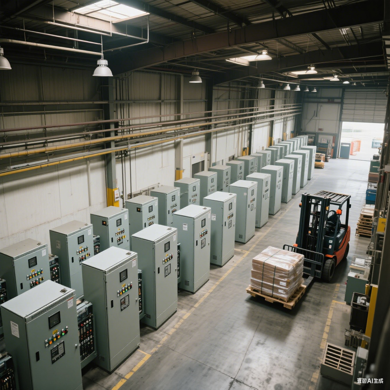
When many cabinets are used together, we can arrange them in two rows—either face-to-face or back-to-back. Face-to-face gives a better view and makes checks easier. If a busbar bridge connects the two rows, we must give the builder an exact plan so they can size it correctly. On-site measuring may be needed.
8. Cabinet Interlocking: The ‘Connector’ for Functions
Most functions can run in one cabinet. But some need two cabinets to work together. In that case, the error-proof lock needs to work across both cabinets. This makes design and setup harder. If the two cabinets are close, we can use a mechanical lock. If they’re far apart, we must use a program lock or electric lock.
From this analysis, we can see that every part of the electrical system closely affects the cabinet structure. In real-world design, we must consider all these factors to build strong, well-laid-out control cabinets. If you have more questions or needs for electrical control cabinet design, feel free to reach out!