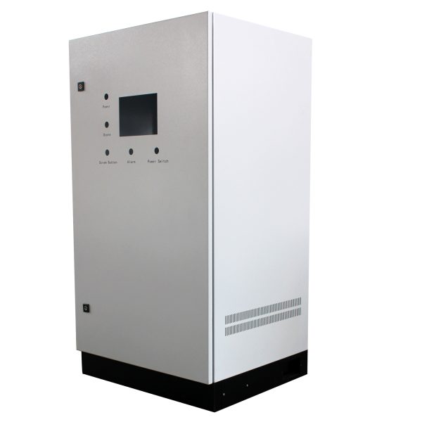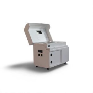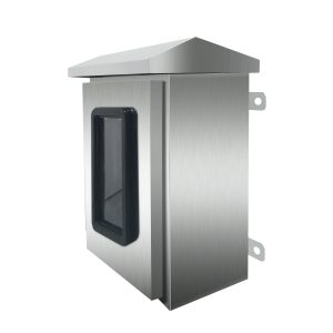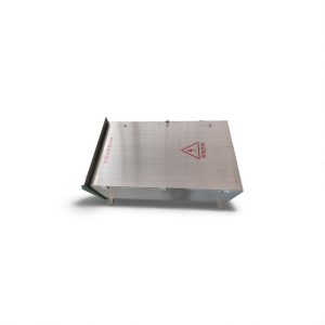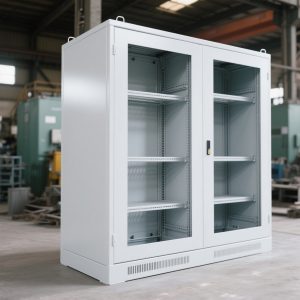

Electrical cabinet drawings translate an equipment layout into information that can be reviewed, quoted, fabricated and inspected. A useful drawing set must cover both the mechanical enclosure and the electrical integration constraints without relying on assumptions that vary between the buyer and manufacturer.
Start With the Equipment and Installation Envelope
Define the overall cabinet size, installation method, access direction, internal equipment, cable routes and service clearances. Record the operating environment, transport constraints and any dimensional limits at the installation site. These inputs determine the basic frame, door arrangement, mounting plate and reinforcement strategy.
Separate General Arrangement and Part Drawings
The general arrangement should show the cabinet envelope, doors, internal layout, mounting interfaces and major accessories. Individual part drawings should then define flat patterns, bends, holes, welds, tolerances and finish notes. Keeping these drawing purposes separate makes reviews easier and reduces the risk of conflicting dimensions.
What a Production Drawing Set Should Contain
- Overall dimensions and datum scheme
- Material grade, thickness and surface finish
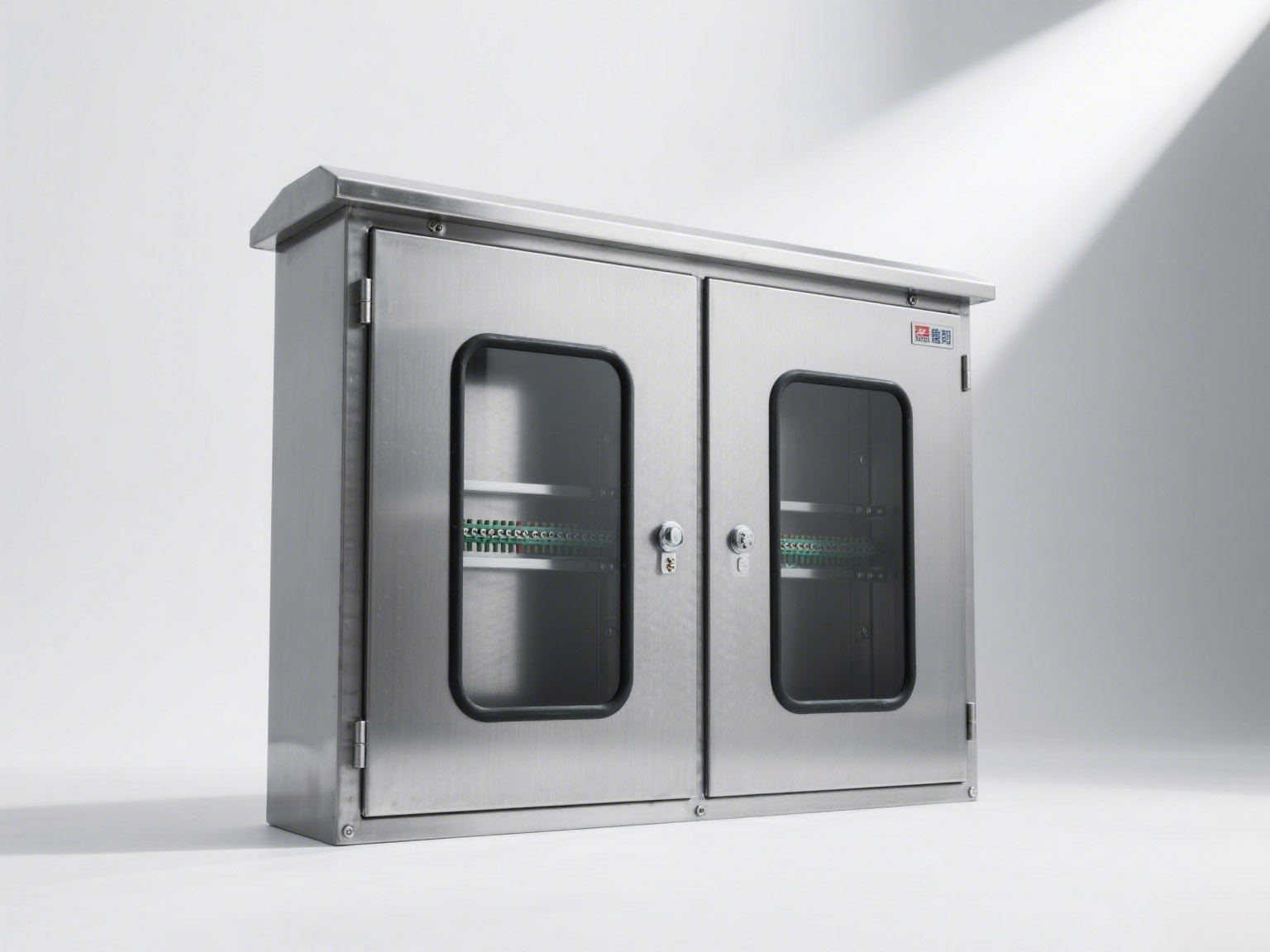
- Door, hinge, lock and gasket arrangement
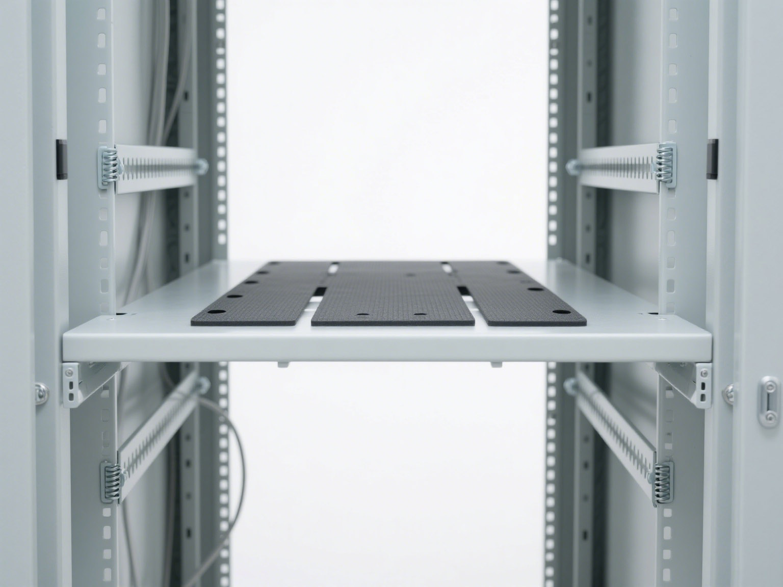
- Mounting plate, rail, bracket and equipment locations
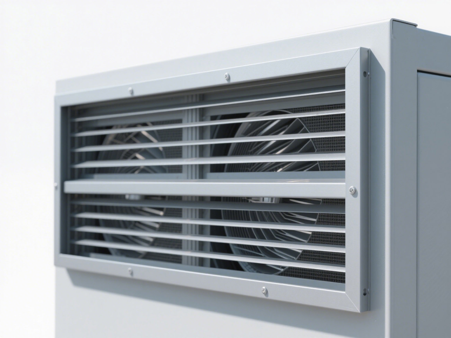
- Cutouts, cable entries, ventilation and lifting points
- Bend direction, weld symbols and critical tolerances
- Grounding or bonding provisions
- Part numbers, quantities and revision status
Use 3D Models to Check Interfaces
A 3D model can help identify collisions, door-swing conflicts, inaccessible fasteners and insufficient wiring space before metal is cut. The model does not replace controlled 2D manufacturing information; it should agree with the drawing revision used for quotation and production. The electrical enclosure 3D design page explains the available drawing workflow.

Review Manufacturability Before Release
Check minimum bend distances, tool access, corner relief, weld access and whether specified tolerances are necessary for function. Review coating allowances at hinges, grounding points, threads and mating features. If multiple processes can meet the requirement, define the functional acceptance criteria rather than prescribing a costly detail without a reason.
Control Revisions and the Bill of Materials
Every drawing, model and BOM should carry an identifiable revision. The BOM should separate fabricated parts, purchased hardware and optional items. Before release, confirm that the same revision is referenced by purchasing, production and inspection. This prevents an updated door or cutout drawing from being paired with an obsolete cabinet model.
Drawing Package for Quotation
Send PDF drawings plus the available native CAD files, expected quantity, finish, applicable standards and required inspection records. Clearly identify open questions and permitted alternatives. Review the documented quality inspection process, then use the contact page to submit the controlled package for quotation.