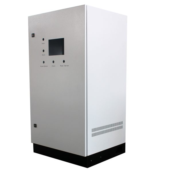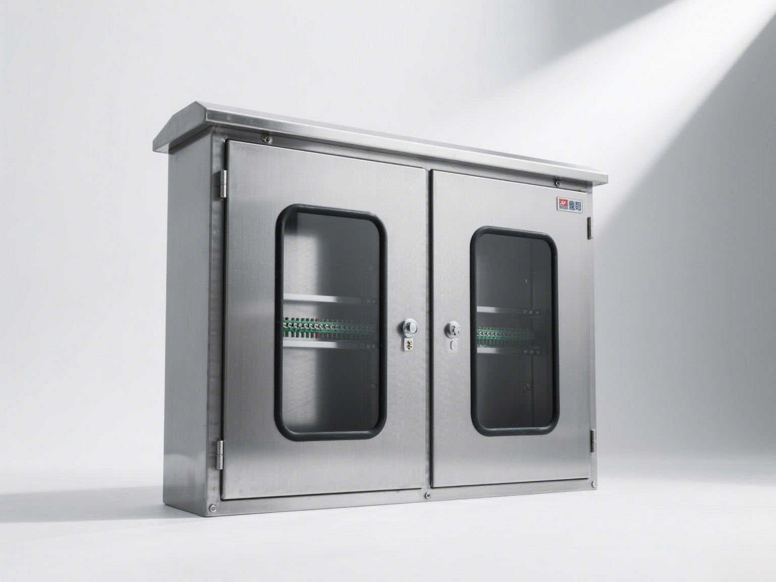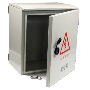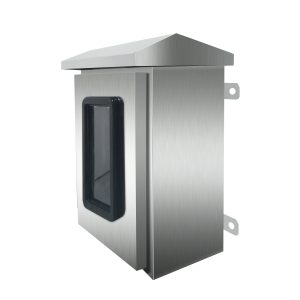

The electrical component layout diagram is the combination of certain electrical components according to specific principles. The design of the electrical component layout diagram is based on the electrical schematic, component drawings, and the division of components. Whether the overall configuration design is reasonable or not affects the manufacturing and assembly quality of the electrical control system. It also impacts the realization of system performance, reliability, and the convenience and quality of operations, commissioning, and maintenance. When designing the electrical component layout diagram, the following principles should be followed:
1. Must comply with relevant national standards
(1) The overall design should meet the electrical control cabinet design standards and regulations while ensuring that the entire electrical control system is centralized and compact.
(2) The overall structure should be clearly drawn, with connections between each unit and the main body shown. While clearly indicating the structure, each unit component can be drawn in a schematic form but should be projected according to the actual size. Generally, front, side, and top views should be drawn, and for complex devices, a rear view should also be included. In short, the main principle is clarity in structure. The diagram should show the cabinet in a cutaway view, with the outline shown separately.
(3) The overall configuration design is expressed in the form of the electrical system’s assembly diagram and wiring diagram. The diagram should schematically show the location of each major component, wiring relationships, wiring methods, and the use of cable trays, ducts, etc. The electrical control cabinet assembly diagram and wiring diagram can be separated or combined, depending on the complexity. The assembly diagram of the electrical control cabinet serves as the basis for designing sub-components and coordinating the parts into a complete system.
(4) The electrical component layout diagram is primarily used to indicate the actual positions of all electrical components on the electrical equipment, providing necessary information for installation and maintenance. The diagram should indicate the relevant installation dimensions, and the component codes should match the ones in the electrical schematic and the list of electrical components. The diagram should reserve at least 10% of additional space and indicate the positions for wires, ducts, or trays for future design modifications.

2.Determining the Position of Electrical Components
(1) Within the space constraints, heat-generating components and parts with significant noise or vibration should be placed as far apart as possible or isolated from other components. Generally, heavier and larger equipment should be placed at the bottom, main circuit components and mounting boards should be installed on the cabinet’s frame, while control circuit components should be mounted on the mounting board. When there are many components, electrical elements and mounting boards can be arranged in layers.
Within the same component, larger and heavier electrical parts should be installed at the bottom of the electrical panel or on the cabinet’s frame, while heat-generating components should be installed at the top or rear of the panel. Load switches should be installed below the isolation switch, ensuring that the center lines of both switches are aligned for easy busbar connections. Typically, thermal relays’ outgoing lines are directly connected to motors, and incoming lines are connected to contactors, ensuring short wiring and better heat dissipation.
(2) Electrical components that require frequent maintenance, inspection, or adjustments should not be placed too high or low. Manually operated switches and instruments that need frequent monitoring should be installed at ergonomic heights for easy operation.
(3) High-voltage and low-voltage wiring should be separated, and attention should be given to the grounding and shielding of wiring to prevent external interference.
(4) To facilitate disassembly and maintenance, wiring between different layers and connections to the external cabinet should be made via terminal blocks (or connectors).
(5) Displays, instruments, indicator lights, switches, and adjustment knobs should be installed at the top of the electrical cabinet door. For large equipment with multiple workstations, the convenience of multi-location operation should also be considered. The main power switch and emergency stop switch of the control cabinet should be placed in easily accessible and visible locations.
(6) The arrangement of electrical components should consider safety gaps, maintaining adequate spacing between components in all directions (top, bottom, left, right), while ensuring neatness, aesthetics, and symmetry. Electrical components with similar dimensions and structures can be grouped together for easier processing, installation, and wiring. If using cable trays, appropriate spacing between components should be maintained to facilitate wiring and maintenance, and factors such as heat dissipation should be considered.

3. Requirements for Drawing Electrical Layout Diagrams
(1) Once the positions of all electrical components have been determined, the electrical layout diagram can be drawn. The layout diagram is based on the outline of the electrical components, marking the spacing dimensions based on the component axis. The installation dimensions and tolerance ranges for each electrical component should be noted according to product specifications to ensure the quality of installation plate processing and the smooth installation of electrical components.
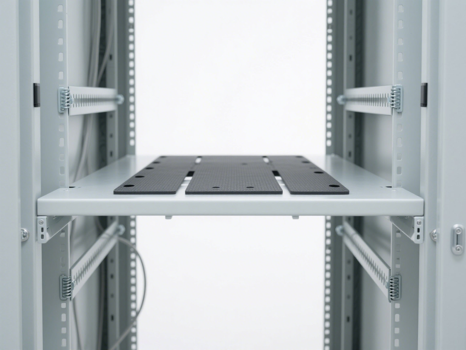
(2) Large electrical components in the electrical cabinet should be installed between two mounting beams. This approach reduces the weight of the cabinet, saves materials, and facilitates installation. Therefore, the longitudinal installation dimensions should be calculated during the design process.
(3) In the electrical layout diagram, the outline of the equipment should be drawn with fine solid lines or dashed lines, and the electrical components should be drawn with thick solid lines to represent simple outlines.
(4) In the electrical layout design, based on the number of incoming and outgoing cables, the wire specifications, and outlet positions, the wiring method and the use of terminal blocks, connectors, or plugs should be selected, with appropriate connection numbers marked on the diagram.
(5) When arranging electrical components, the technical requirements for electrical connections should be followed. For example, the main busbar should not intersect, and wiring should be as short as possible. Avoid the practice of taking long paths when shorter ones are available.
(6) Based on the electrical control cabinet assembly diagram, final decisions on the external dimensions of the cabinet, internal structure, positions of structural parts, and the shape and dimensions of the control panel should be made.