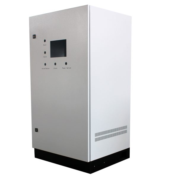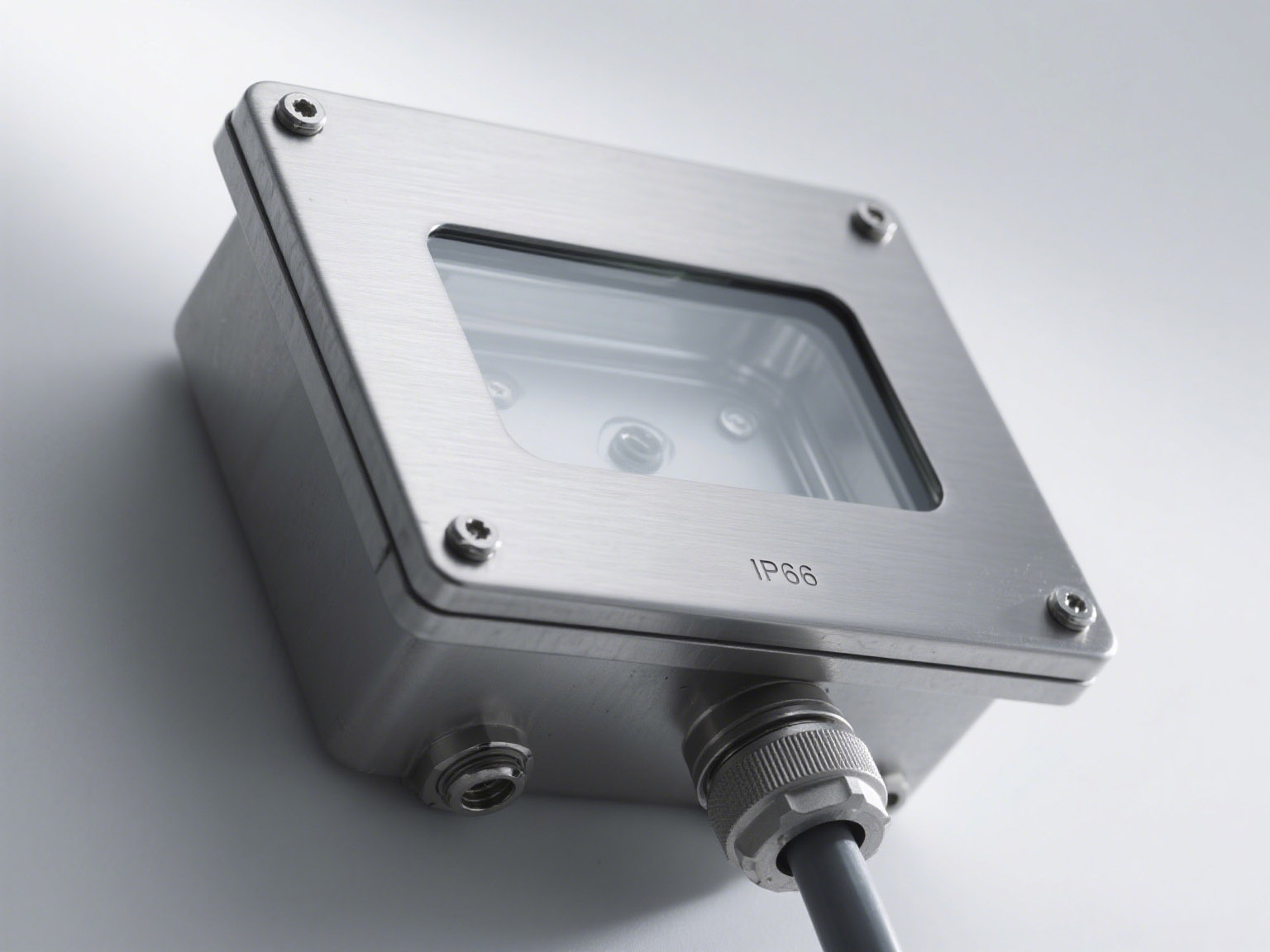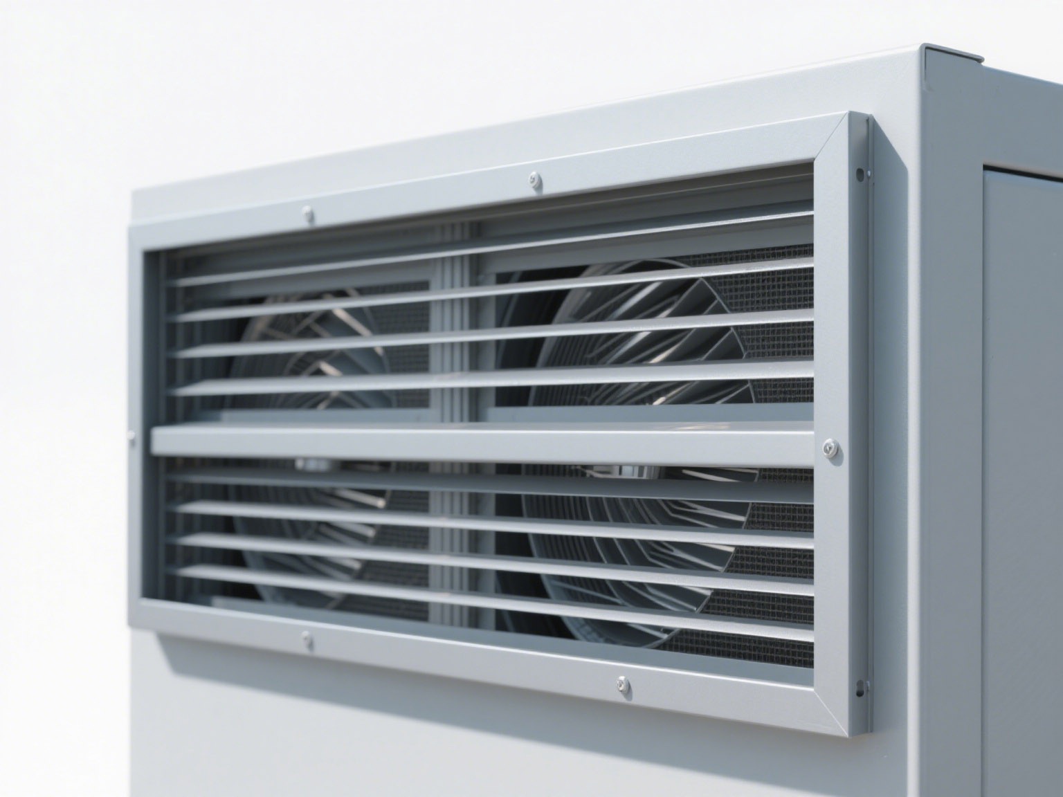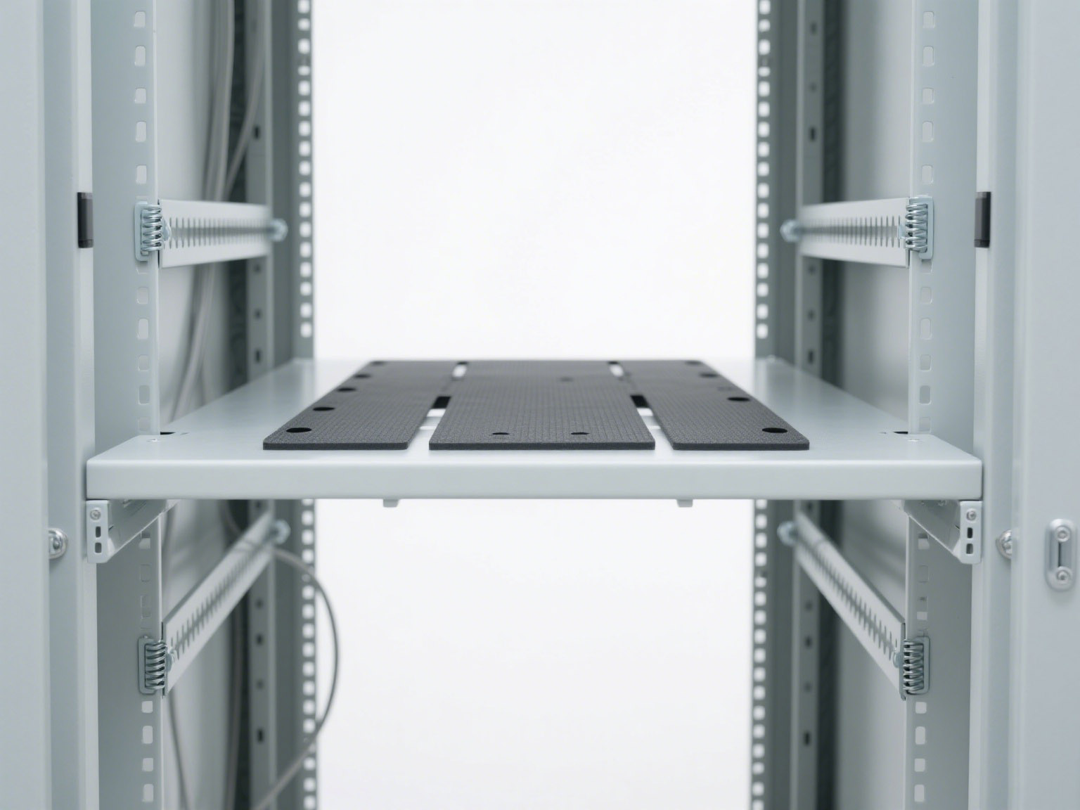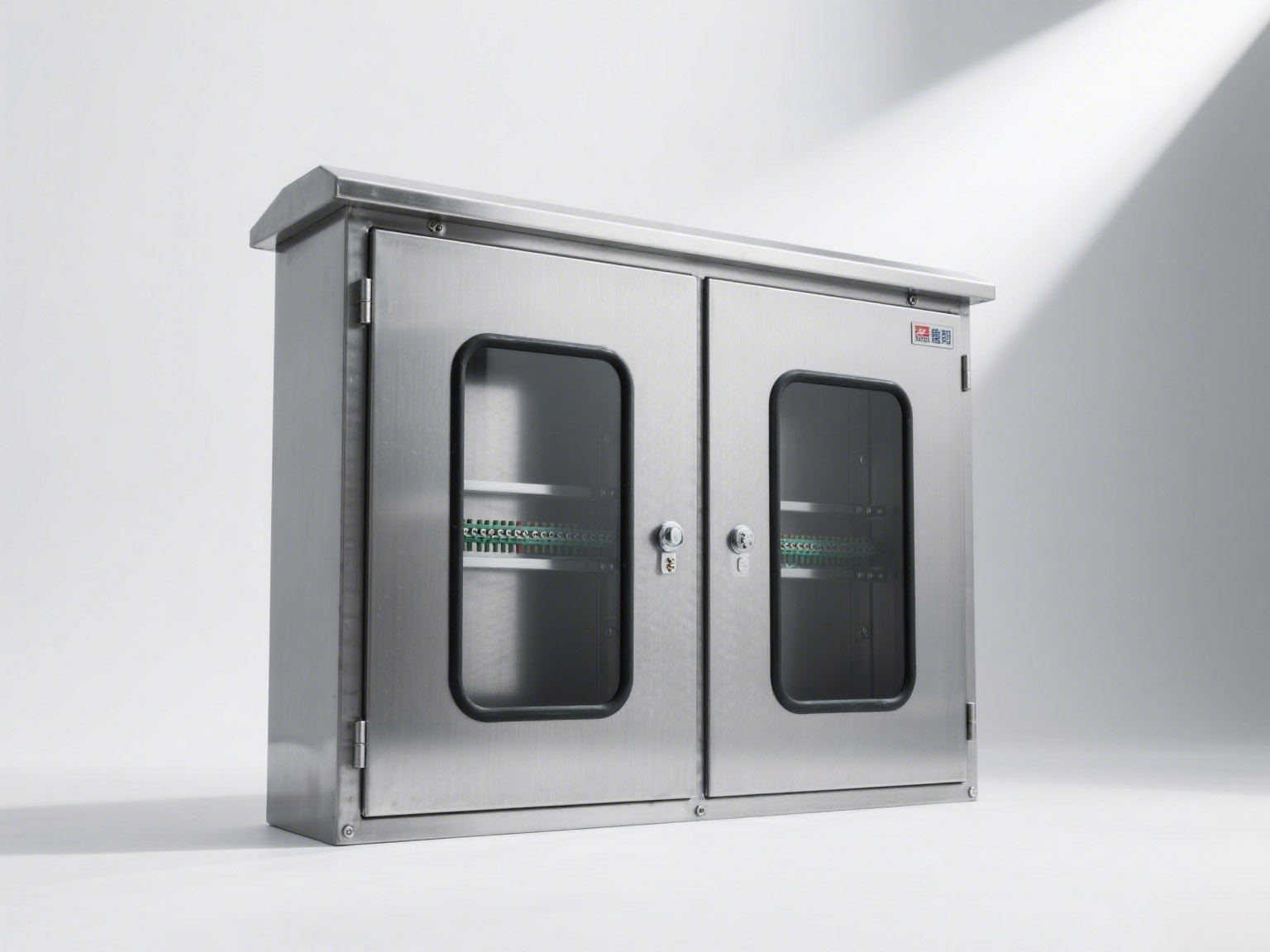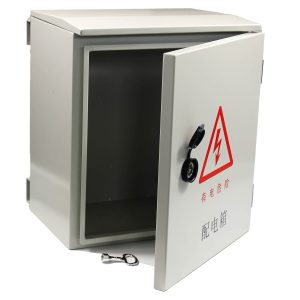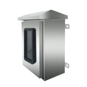
Electrical cabinet grounding and bonding must be planned with the complete electrical assembly, not treated as a feature of the sheet-metal shell alone. The enclosure provides the mechanical structure and conductive surfaces, while the system designer remains responsible for protective-conductor sizing, component selection, fault protection, verification and any required certification of the finished assembly.
Updated October 12, 2026: this guide now includes internal arc-fault considerations following the publication of IEC TS 61641:2026 and recent industry work on higher-power electrical systems.
Define the enclosure supplier’s scope
Begin by stating whether the order covers an empty enclosure, a cabinet with a mounting plate, fabricated panels and brackets, a partial mechanical assembly, or a fully populated electrical assembly supplied by another organization. The answer determines who owns the electrical design, protective devices, conductor sizing, assembly verification and certification.
Anstorm manufactures fabricated metal enclosure shells and cabinet bodies. A metal shell should not be described as a certified switchgear or controlgear assembly unless the exact finished configuration has the required evaluation and supporting evidence. The RFQ should identify the responsible system integrator and list the drawings and verification records expected from each supplier.
Plan the protective earth path before fabrication
Show the main protective earth connection and all required bonding points on the approved drawing. Typical interfaces may include doors, removable panels, mounting plates, gland plates, frames and separately attached structural parts. The locations must remain accessible for installation, inspection and maintenance after equipment is fitted.
Specify studs, terminals, washers and retention methods appropriate to the project. Hinges should not automatically be treated as a reliable protective bond. If a door or removable cover requires bonding, the system designer should define a dedicated flexible bonding connection or another verified solution.
Control paint, powder coating and conductive interfaces
Powder coating, paint and surface oxides can interrupt metal-to-metal continuity. Fabrication drawings should identify masked areas, contact zones or suitable bonding hardware wherever an electrical connection is required. These areas also need corrosion control that does not defeat the intended conductive interface.
Include the required continuity checks and acceptance criteria in the inspection plan. A visual check alone cannot confirm the performance of a protective bonding path. The completed assembly should be verified using the applicable product standard and the system manufacturer’s test procedure.
Coordinate clearance, creepage, barriers and cable routes
Electrical clearances and creepage distances depend on system voltage, insulation design, pollution conditions, overvoltage category and the applicable assembly standard. The enclosure supplier needs the approved equipment layout, not a generic cabinet size, before cutting openings or placing supports.
Provide space for cable bending, termination, ducts, protective devices and service access. Keep conductors away from sharp edges and moving parts. Power, control and communication routes may require separation, shielding or controlled crossings. Grounding and EMC measures should be defined from the system architecture rather than inferred from the cabinet material.
What IEC TS 61641:2026 changes for an enclosure RFQ
IEC TS 61641:2026 addresses methods for verifying the ability of low-voltage switchgear and controlgear assemblies to limit personnel risk and damage during an internal arc fault and to improve power availability afterward. It considers internal overpressure on doors and covers, thermal effects, hot gases, glowing particles and the operation of integrated arc-fault mitigation systems. The publication replaces IEC TR 61641:2014 and IEC TS 63107:2020.
This does not mean that every empty enclosure requires or passes an IEC TS 61641 verification. The technical specification applies to the completed assembly and does not replace the relevant product standard. However, when the buyer’s project calls for internal arc-fault verification, enclosure decisions can affect the test configuration. Door construction, covers, partitions, fasteners, pressure-relief paths, cable compartments and the direction of discharged gases must be defined before metalwork is released.
UL Solutions also noted on October 7, 2026 that higher-voltage DC architectures for data centers introduce new protection, insulation, grounding and enclosure considerations as standards and guidance evolve. The practical lesson is the same: higher power density should lead to a better-defined system RFQ, not an unsupported safety claim about an empty cabinet. Read the UL Solutions overview.
Internal arc information to request from the system designer
- Applicable assembly standard and verification objective: identify the required standard, edition, test scope and responsible certification or test organization.
- Fault and operating data: provide the rated voltage, prospective fault level, protection clearing time and operating conditions used by the system designer.
- Assembly arrangement: define compartments, partitions, doors, covers, component layout and cable-entry zones for the actual configuration.
- Pressure and exhaust strategy: show pressure-relief features, intended gas paths, clearances and areas that personnel must not occupy.
- Access category and service conditions: describe who can approach the equipment, where it will be installed and whether access changes during maintenance.
- Change control: state which substitutions or dimensional changes require renewed engineering review or verification.
An enclosure quotation cannot establish these inputs on the buyer’s behalf. They must come from the responsible electrical designer or system manufacturer. Anstorm can use approved mechanical drawings to review fabrication details within its metal-enclosure scope.
Prepare a verification-ready cabinet RFQ
A useful RFQ should include:
- Overall dimensions, equipment layout, mounting points and fabrication tolerances.
- Material grade, sheet thickness, surface finish and environmental exposure.
- Door, cover, partition, locking and removable-panel requirements.
- Grounding and bonding drawing, including masked conductive interfaces.
- Cable-entry, gland-plate, busbar-interface and service-access details.
- Applicable standards, inspection records and responsibility for complete-system verification.
- Any internal arc-fault requirements, including the tested configuration and permitted changes.
Use the electrical cabinet specification checklist to organize the drawing package, then review the broader electrical cabinet functional requirements. For fabrication controls, see the metal enclosure manufacturing checklist.
Keep enclosure claims separate from assembly verification
Grounding provisions, doors, partitions and pressure-management features can support the intended assembly design, but their presence does not prove compliance by itself. Ratings and certification belong to the exact evaluated configuration. Component changes, new openings or different installed equipment can affect the result.
Review available electrical control cabinet configurations, or send Anstorm your mechanical drawings for a fabrication review. Include the responsible system designer’s requirements so the enclosure scope, interfaces and verification documents are clear before production.